DFM Sheet Metal Guide: 2026 Engineering Standards
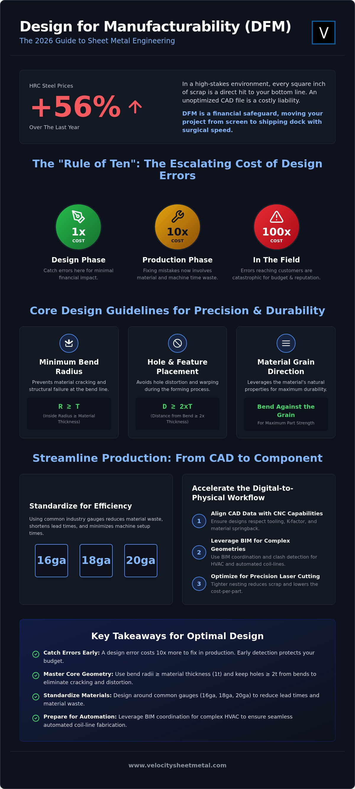
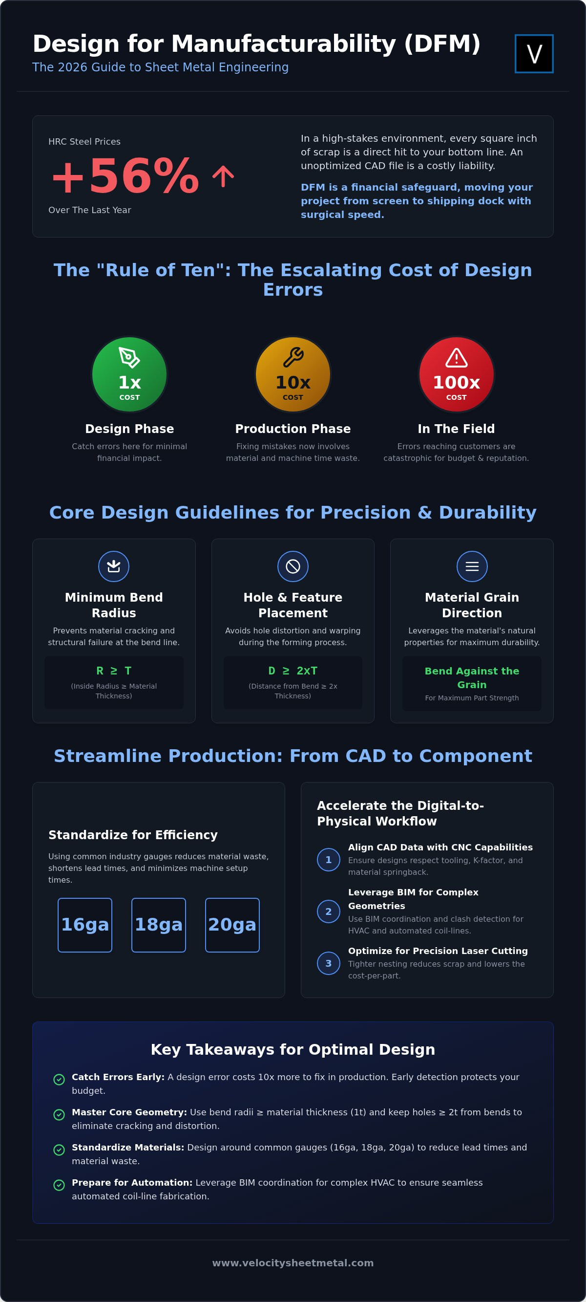
HRC Steel prices have surged by nearly 56% over the last year, making every square inch of scrap a direct hit to your bottom line. In this high-stakes environment, your CAD file is either a strategic asset or a costly liability. If you aren't optimizing for the shop floor from the first click, you're paying for metal that ends up in the bin. This design for manufacturability sheet metal guide provides the technical roadmap needed for the 2026 engineering landscape. We focus on surgical precision to protect your margins and your schedule.
You likely feel the pressure of tightening lead times and the frustration of constant back-and-forth with the fab shop. It's a common bottleneck that stalls innovation and inflates project costs. This guide will help you master core DFM principles to slash production costs, eliminate repetitive redesigns, and accelerate the transition from a digital model to a finished component. We'll preview the latest standards for bend radii and laser tolerances while showing how BIM coordination bridges the gap between complex designs and automated coil-line production. Let's get to work.
Key Takeaways
- Learn why catching a design error early costs ten times less than fixing it during the production phase.
- Use this design for manufacturability sheet metal guide to master bend radii and relief techniques that eliminate material cracking.
- Reduce lead times and material waste by standardizing your designs around common industry gauges like 16ga, 18ga, and 20ga.
- Leverage BIM coordination and clash detection to prepare complex HVAC geometries for seamless automated coil-line fabrication.
- Accelerate your digital-to-physical workflow by aligning CAD data with modern CNC press brake and laser cutting capabilities.
The Fundamentals of Design for Manufacturability (DFM) in Sheet Metal
Design for Manufacturability (DFM) is the engineering practice of designing parts to be easy and cost-effective to produce without sacrificing functional integrity. In sheet metal, this means aligning your digital geometry with the physical limits of the press brake and laser cutter. This design for manufacturability sheet metal guide emphasizes that DFM isn't just a suggestion; it's a financial safeguard. It moves your project from the screen to the shipping dock with surgical speed.
Engineers often reference the 'Rule of Ten.' It's a simple, brutal reality of manufacturing: a design error caught during production costs ten times more than one caught during the initial design phase. If that error reaches the field, the cost multiplies again. By the time a part reaches the shop floor, material has been purchased and machine time is already ticking. Catching a tight bend radius or a missing relief early keeps your budget intact.
Modern 2026 manufacturing favors automation-first design protocols. With HRC steel prices rising 55.93% year-over-year, efficiency is mandatory. You must also account for grain direction. Metal isn't isotropic. Bending against the grain provides maximum strength, while bending with the grain increases the risk of cracking and structural failure. Proper DFM ensures your part orientation leverages the material's natural properties for maximum durability.
Bridging the Gap Between CAD and the Shop Floor
Moving from digital intent to physical reality requires more than a clean STEP file. Precision laser cutting can execute complex profiles, but CAD models often ignore material springback or the specific 'K-factor' of a shop's tooling. A 'perfect' model in your software might be unbendable on a CNC press brake. That's where the manufacturing engineer steps in. Their technical review ensures that your design respects the physical properties of the alloy before the first spark flies. This process transforms a theoretical concept into a repeatable, high-quality product.
The Economic Impact of DFM on Production Timelines
Standardized designs slash machine setup times and minimize tooling changes. When you optimize for precision laser cutting services, you get tighter nesting. This reduces scrap and drives down the cost per part. For national OEM accounts, these small efficiencies compound across thousands of units. DFM directly shortens lead times by removing the administrative friction of back-and-forth design revisions. It streamlines the workflow, moving you from raw coil to finished assembly without the typical industry delays.
Core Design Guidelines for Precision Bending and Laser Cutting
Precision in sheet metal isn't a suggestion. It's a physical requirement. This design for manufacturability sheet metal guide focuses on the specific geometric rules that keep your parts within spec and your production costs low. If your design ignores the physical limits of the press brake or laser, you'll face cracked corners, distorted holes, and wasted material. We build for reality, not just for the CAD environment.
The first rule of precision bending is the minimum bend radius. As highlighted in this Sheet Metal Design Handbook, your internal radius should generally be equal to or greater than the material thickness (1t). Designing with a radius smaller than 1t causes the metal to stretch beyond its tensile limit. This leads to fractures on the outer surface and structural instability. For heavy-gauge steel, increasing this radius is often necessary to maintain integrity.
Hole and slot placement is equally critical for maintaining part geometry. Keep all features at a distance of at least twice the material thickness (2x) from any bend line. Placing a hole too close to a bend causes the aperture to stretch into an oval as the metal flows during the forming process. Balancing these precision requirements with realistic manufacturing capabilities prevents the cost spikes associated with over-engineering and unnecessary secondary operations.
Bend Radii and Reliefs: Avoiding Material Stress
Calculating an accurate K-factor is essential for flat pattern development. It determines how much the material stretches during the bend. By standardizing your bend angles, you minimize common press brake forming defects such as springback or crowning. When designing for heavy-gauge components, use bend reliefs to prevent tearing at the corners. A 'V' relief is standard for most industrial applications, but circular reliefs provide superior stress distribution for parts subject to high vibration or fatigue. These small geometric choices prevent catastrophic part failure.
Laser Cutting Optimization: Holes, Slots, and Tabs
High-speed laser cutting requires specific considerations for stability and heat management. Aim for a maximum hole-to-thickness ratio of 1:1 for steel and 1.5:1 for aluminum. If you design holes smaller than the material thickness, the laser may struggle to clear the dross. This leads to poor edge quality and potential slag buildup. Use micro-tabs to secure small parts within the nest during high-speed runs. This prevents parts from tipping and damaging the laser head. Avoid narrow webs between features. If the metal between two cuts is too thin, it will overheat and warp, ruining the part's dimensional accuracy. If you're looking to scale production, consult with our technical team to ensure your CAD files are optimized for our automated lines.
Material Selection and Gauge Optimization for Scalability
Material selection is the foundation of any successful design for manufacturability sheet metal guide. While geometry defines the part's shape, the material dictates its cost, weight, and production speed. In late 2026, with HRC steel prices sitting at approximately $1,263 per ton, choosing the wrong gauge isn't just an engineering error; it's a financial drain. Standardizing your designs around common industry gauges like 16ga, 18ga, and 20ga ensures better material availability and lower cost per part. It also simplifies machine setup, moving your project through the shop floor faster.
Thickness significantly impacts CNC press brake services for OEMs. Heavier gauges require larger V-dies and higher tonnage, which can limit the complexity of your bends. Conversely, thinner materials are prone to warping and require specialized handling to maintain structural integrity. Beyond the shop floor, material choice dictates your logistics strategy. For national distribution, reducing a part's weight by optimizing gauge can result in substantial shipping savings without compromising performance. It's about finding the sweet spot where strength meets efficiency.
Choosing the Right Alloy for Structural Integrity
Your application determines your alloy. Galvanized steel remains the standard for HVAC ductwork due to its corrosion resistance and cost-effectiveness. Stainless steel is the go-to for food-grade or harsh industrial enclosures where hygiene and durability are paramount. Aluminum offers weight advantages but presents unique DFM challenges. It has a higher spring-back rate than steel and a delicate surface finish that requires protective masking during laser cutting. As noted in this Design for Manufacturing (DFM) guide, understanding these cost-to-strength ratios early prevents expensive pivot points during the fabrication cycle.
Standardizing Gauges to Reduce Coil-Line Waste
High-volume coil line duct fabrication thrives on consistency. When you implement a 'Consolidated Gauge' strategy, you design across fewer thicknesses to reduce inventory costs and coil changeover times. This approach is essential for large-scale rectangular ductwork. Using a consistent gauge ensures that automated lines run at peak efficiency without the downtime associated with re-tooling for non-standard materials. It stabilizes the production rhythm. This guarantees that your national accounts receive parts with uniform structural rigidity across every production run, regardless of the order volume.
Advanced DFM for HVAC: Leveraging BIM and Automated Coil Lines
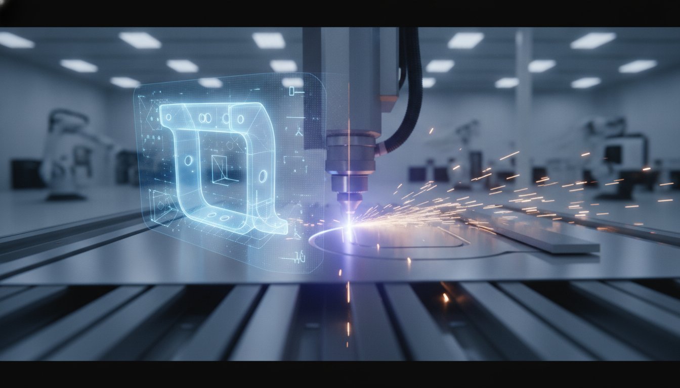
In the HVAC sector, a design for manufacturability sheet metal guide shifts focus from individual part geometry to system-wide throughput. High-volume projects require a digital-to-physical bridge that only automation provides. This is where the automated coil line becomes the engine of your production strategy. By aligning your CAD data with machine logic, you eliminate the manual bottlenecks that traditionally stall mechanical projects. It moves your project from the screen to the duct hanger with surgical speed.
Efficiency starts with standardization. Designing rectangular ductwork around 5-foot or 6-foot sections allows the coil line to run at peak capacity. It minimizes material drops and reduces the number of joints required in the field. Custom transition fittings must be engineered for both laminar airflow and rapid assembly. These components are the critical links in a high-performance system. If they aren't optimized for the shop floor, they become the primary cause of project overruns.
Rectangular Ductwork: Designing for Automation
Optimizing TDC/TDF flange designs ensures your ductwork is ready for rapid field connection immediately after fabrication. Automated longitudinal seams, such as Pittsburgh or snap-locks, require precise design tolerances to maintain a pressurized seal. Smart layouts can also incorporate integrated turning vanes during the initial cut. This reduces the need for manual secondary operations. It keeps the workflow moving from the coil straight to the shipping pallet without unnecessary administrative delays.
BIM Coordination: Eliminating Field Collisions at the Design Phase
BIM clash detection for HVAC fabrication serves as the ultimate DFM filter. It identifies structural collisions in the virtual environment before you buy a single pound of galvanized steel. Using spool drawings, you can move seamlessly from a coordinated 3D model to HVAC duct fabrication for mechanical contractors. This digital precision allows for the use of 'total station' points, ensuring that hangers and sleeves are placed with surgical accuracy on the job site. BIM-integrated workflows are documented to reduce field waste by up to 30%. This level of coordination transforms the job site from a fabrication zone into an assembly point.
Partner with Velocity Sheet Metal to leverage our BIM coordination and automated coil-line capabilities for your next national account.
Partnering with Velocity Sheet Metal for National OEM Production
Velocity Sheet Metal operates as an authoritative expert in the precision fabrication space. We don't just process files; we perform a rigorous technical design review on every project. This design for manufacturability sheet metal guide serves as our internal benchmark for every OEM part and HVAC component we produce. By identifying unmanufacturable geometries or non-standard material choices early, we protect your margins and your schedule. We move you from the administrative delays of typical shops to a streamlined, automated workflow. Our pragmatic approach ensures your CAD data translates perfectly to the shop floor.
Scaling a project requires more than just machines. It requires a partner who understands the industrial reality of production. We act as the essential bridge between a digital file and a tangible product. Our team focuses on efficiency, reliability, and technical capability. We value your time as much as our own precision. When you partner with us, you gain access to a workflow designed for speed and accuracy. From the initial digital input to the final logistics of delivery, every step is controlled and repeatable.
From Digital Spool Drawings to Automated Execution
Our facility transforms digital spool drawings into automated execution with surgical precision. We leverage an automated coil-line for rectangular duct and high-speed custom laser cutting for complex OEM parts. With 50+ years of combined management experience, our team has seen every failure point in sheet metal design. We use that expertise to solve DFM challenges that software often misses. We help OEM partners scale from a single prototype to high-volume production runs without losing dimensional accuracy. This rapid transition is the result of aligning modern technology with decades of hands-on workshop experience.
National Logistics and Standardized Production
Consistency is the foundation of national OEM production. Velocity ensures that every part meets the same strict DFM standards, whether it's shipping to a site near our registered office or across the United States. We provide standardized production for national accounts to ensure project consistency from the first part to the 10,000th. By leveraging our BIM coordination and spool drawing services, we streamline complex commercial projects nationwide. Our national shipping capabilities mean your optimized designs are delivered on time. We eliminate the variability that plagues traditional fabrication, giving you a reliable partner for large-scale industrial growth. We are ready to get to work immediately on your most demanding specifications.
Standardize Your Digital-to-Physical Workflow
Mastering the principles in this design for manufacturability sheet metal guide is the most effective way to protect your margins in a volatile metal market. Standardizing material gauges and leveraging BIM coordination eliminates the friction that typically stalls large-scale commercial installs. Every design choice must move you closer to automated efficiency, not further into manual rework. When you align your digital intent with the physical realities of the shop floor, you ensure a repeatable and scalable production cycle.
Velocity Sheet Metal is ready to act as your technical partner. We combine 50+ years of management experience with automated coil-line efficiency to deliver precision at scale. Whether you're designing complex OEM parts or high-volume HVAC ductwork, our national shipping capabilities ensure your project stays on track regardless of your location. Don't let unmanufacturable geometry or administrative delays slow your operation. We focus on surgical accuracy to move your components from raw coil to the shipping dock with maximum speed.
Request a Technical Design Review from Velocity Sheet Metal today and bridge the gap between your digital concept and a finished product. We are ready to help you scale.
Frequently Asked Questions
What is the most common DFM mistake in sheet metal design?
The most common mistake is placing holes or slots too close to a bend line. Features should be at least twice the material thickness from any bend to prevent distortion or hole stretching. Another frequent error is ignoring the grain direction of the metal. Bending with the grain can lead to cracking. Our technical design review process catches these issues before they reach the CNC press brake, ensuring your parts remain structurally sound.
How does material thickness affect the minimum bend radius?
Material thickness dictates the minimum internal bend radius to prevent fracturing. As a general rule, your internal radius should be at least equal to the material thickness. For heavy-gauge steel, you often need to increase this radius to accommodate the material's limited elasticity. Using a radius that is too tight causes the outer surface to stretch and crack. This compromises the integrity of the entire component during high-speed production runs.
Why is BIM coordination considered part of the DFM process for HVAC?
BIM coordination serves as the digital filter for DFM in complex HVAC systems. It identifies structural collisions and clearance issues in a virtual environment before fabrication begins. By using spool drawings, we ensure that every duct section is optimized for our automated coil line. This process reduces field waste and ensures that components fit perfectly on the first try. It transforms the job site into an assembly point rather than a fabrication zone.
Can I use the same DFM rules for aluminum and stainless steel?
You cannot use identical DFM rules for aluminum and stainless steel because their physical properties differ significantly. Aluminum has a higher spring-back rate and is more prone to surface marking. Stainless steel is much harder and requires more tonnage for bending. This design for manufacturability sheet metal guide recommends adjusting your K-factors and bend reliefs based on the specific alloy. These adjustments ensure that your CAD model translates accurately to the finished physical part.
How does designing for an automated coil line differ from manual fabrication?
Designing for an automated coil line requires strict standardization of duct lengths and flange types. Unlike manual fabrication, where custom lengths are common, automation thrives on 5-foot or 6-foot sections to maximize throughput. You must also account for automated longitudinal seams like Pittsburgh locks. This approach minimizes material drops and setup times. It allows for high-volume production that manual shops cannot match, especially when servicing national accounts with tight schedules.
What are the standard tolerances for precision laser cutting in 2026?
In 2026, precision laser cutting typically achieves tolerances of +/- 0.005 inches for most standard gauges. However, these tolerances can vary based on material type and thickness. Thicker plates may require a slightly wider margin to account for the laser's kerf and heat-affected zone. Designing with realistic tolerances prevents unnecessary cost spikes. It allows our high-speed automated equipment to maintain consistency across thousands of parts while ensuring seamless integration with your final assembly.
How can I reduce the cost of my sheet metal parts through design?
Standardizing your designs around common material gauges like 16ga, 18ga, or 20ga is the most effective way to lower costs. This "Consolidated Gauge" strategy lowers inventory expenses and minimizes machine setup time. Additionally, reducing the number of unique bend angles on a single part simplifies the CNC press brake process. High-volume parts should also utilize micro-tabs and optimized nesting to minimize scrap. These small design adjustments compound into significant savings across national OEM production runs.
What is a K-factor and why does it matter for my CAD model?
Including an accurate K-factor in your CAD model is vital for generating a precise flat pattern. The K-factor is a ratio that represents the location of the neutral axis relative to the material thickness. It determines how much the metal stretches during a bend. Without it, your finished part dimensions will be incorrect once formed. This design for manufacturability sheet metal guide emphasizes that using the correct K-factor ensures a perfect fit during final assembly.