BIM Ductwork Coordination: 2026 HVAC Workflow Guide
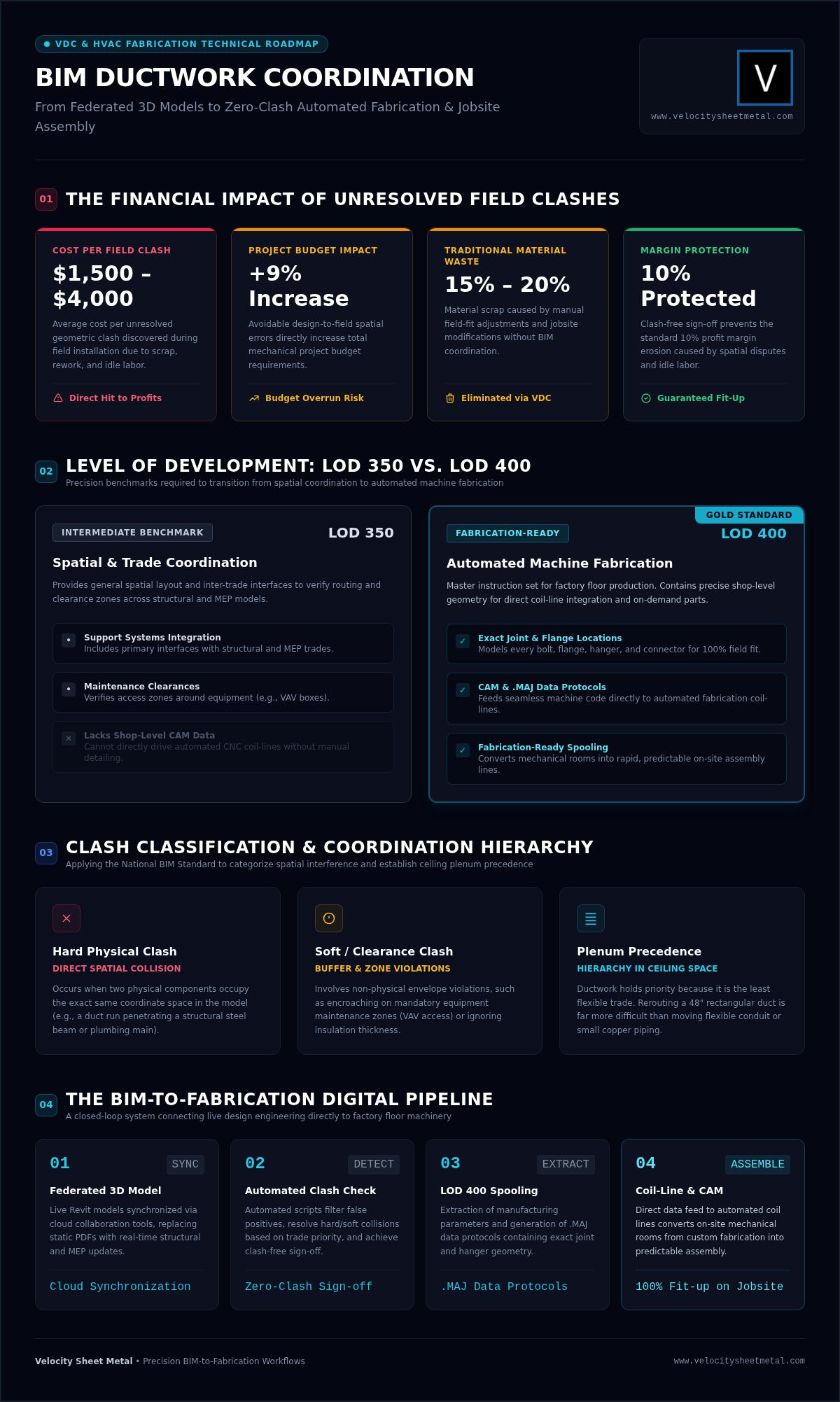
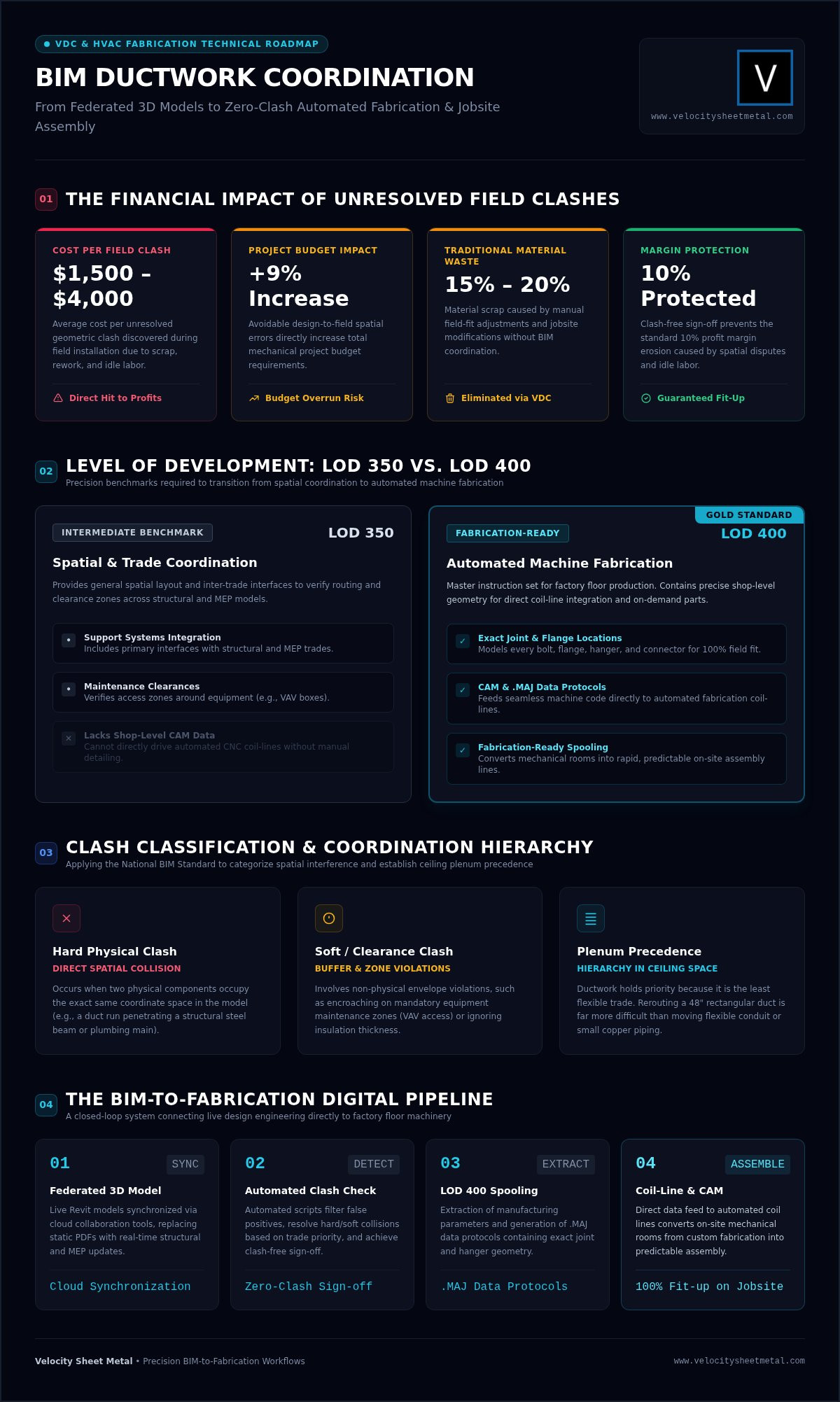
An unresolved geometric clash discovered during field installation costs an average of $1,500 to $4,000 in scrap, rework, and idle labor. For mechanical contractors, these avoidable errors represent a 9% project budget increase and a direct hit to annual profit margins. You've likely felt the frustration of a disconnected workflow where design intent fails to translate to the fabrication shop. It's a bottleneck that slows down your team and creates unnecessary waste.
Mastering bim ductwork coordination is the only way to protect your bottom line in 2026. This guide provides a technical roadmap to integrate high-fidelity modeling with automated fabrication. You'll learn how to move from a federated model to a zero-clash installation using LOD 400 standards and seamless .MAJ data protocols. We're breaking down the workflow from the initial digital concept to the final physical product. We'll cover everything from automated coil-line integration to the precision of spool drawings, ensuring your next project runs with the efficiency of a modern production line.
Key Takeaways
- Identify the critical difference between hard physical intersections and soft maintenance clearance zones to ensure 100% field compliance.
- Eliminate fabrication waste by using bim ductwork coordination to feed precise data directly from your digital model to automated coil-lines.
- Leverage a standardized VDC workflow to scale HVAC production across national project portfolios while maintaining surgical precision.
- Shift from manual shop drawings to fabrication-ready spooling that transforms on-site installation into a predictable assembly process.
- Bridge the gap between design teams and the factory floor to reduce human error and accelerate fabrication-to-site timelines.
What is BIM Ductwork Coordination and Why Does It Matter in 2026?
At its core, bim ductwork coordination is the digital process of modeling, identifying, and resolving spatial conflicts in HVAC systems before fabrication begins. It isn't just about making a 3D drawing. It's about building the project twice: once in a virtual environment and once on the jobsite. By the time the first rectangular duct is loaded onto a truck, every bolt, flange, and hanger has already been cleared for installation. This methodology relies on the broader principles of building information modeling (BIM), where data-rich elements replace generic lines on a page.
The industry has moved beyond basic clash detection. In 2026, we've transitioned to fully integrated Virtual Design and Construction (VDC). This shift means the model is no longer a reference; it's the master instruction set for the factory floor. Traditional duct projects often suffer from 15% to 20% material waste due to field-fit adjustments and rework. Coordination eliminates this overhead. It turns the mechanical room into an assembly site rather than a custom fabrication shop.
The Evolution of VDC in Sheet Metal Fabrication
Modern fabrication doesn't happen in a vacuum. Cloud-based collaboration tools now synchronize the design engineer and the fabrication shop in real time. We've moved from static PDF submittals to live Revit models that reflect every structural change as it happens. This digital-to-physical handshake ensures that the ductwork arriving on site matches the actual field conditions, not an outdated blueprint. In high-volume commercial projects, this speed is non-negotiable. It keeps the schedule moving and the installers productive.
Key Terminology: LOD 350 vs. LOD 400
Understanding the Level of Development (LOD) is critical for project success. While many firms stop at LOD 300, 2026 standards demand more precision. We focus on two primary benchmarks:
- LOD 350: The model includes support systems and interfaces with other trades. It's used for general spatial coordination and ensuring maintenance clearances are respected.
- LOD 400: This is the gold standard for automated fabrication. It contains specific shop-level geometry, including exact joint locations and CAM manufacturing parameters.
Choosing the right level of detail prevents model lag where the digital file lacks the data needed to drive an automated coil-line. For contractors looking to eliminate field collisions, LOD 400 provides the surgical precision required for on-demand part production. It bridges the gap between a design concept and a tangible, installable product.
Eliminating Field Collisions: The Power of HVAC Clash Detection
Field collisions are profit killers. When a duct run hits a structural beam or a plumbing main, the schedule stops. In the traditional workflow, these errors aren't found until an installer is on a lift. Research indicates that resolving a clash in the field costs between $1,500 and $4,000 per instance. Digital bim ductwork coordination identifies these "impossible" runs before a single sheet of metal is cut. This proactive approach relies on the National BIM Standard-United States to ensure every trade uses consistent data protocols during the modeling phase.
Effective clash detection distinguishes between hard and soft interferences. A hard clash occurs when two components occupy the same physical space. A soft clash involves clearance violations, such as encroaching on a VAV box's maintenance zone or ignoring mandatory insulation thickness. Modern coordination software runs automated checks across HVAC, plumbing, electrical, and structural models. This federated view ensures 100% fit-up on the job site, slashing field labor and eliminating the need for on-site modifications. It's the difference between a project that flows and one that stalls.
Automated Clash Resolution Workflows
Coordination follows a strict hierarchy. Ductwork usually takes precedence in the ceiling plenum because it's the least flexible trade. Moving a 48-inch rectangular duct is significantly harder than rerouting a conduit or a small-diameter copper pipe. We use automated scripts to filter out false positives and identify recurring conflict patterns across the floor plan. This systematic review leads to a "clash-free" sign-off. It's the mandatory green light that guarantees every piece will fit exactly as modeled. This step alone prevents the typical 10% erosion in profit margins caused by spatial disputes and idle labor.
Spool Drawings: The Bridge Between Model and Shop Floor
Once the model is coordinated, it must be translated into actionable data through mechanical spooling services. Spooling is the granular breakdown of duct runs into individual, shippable components. Accuracy at this stage is the single biggest factor in installation speed. Every spool drawing includes precise dimensions, joint types, and labeling that matches the digital model. This process transforms a complex design into a kit of parts ready for our automated coil-lines. If you're ready to improve your workflow, our team can help you transition from a coordinated BIM file to precision-fabricated duct with surgical accuracy.
From Model to Machine: Integrating BIM with Automated Fabrication
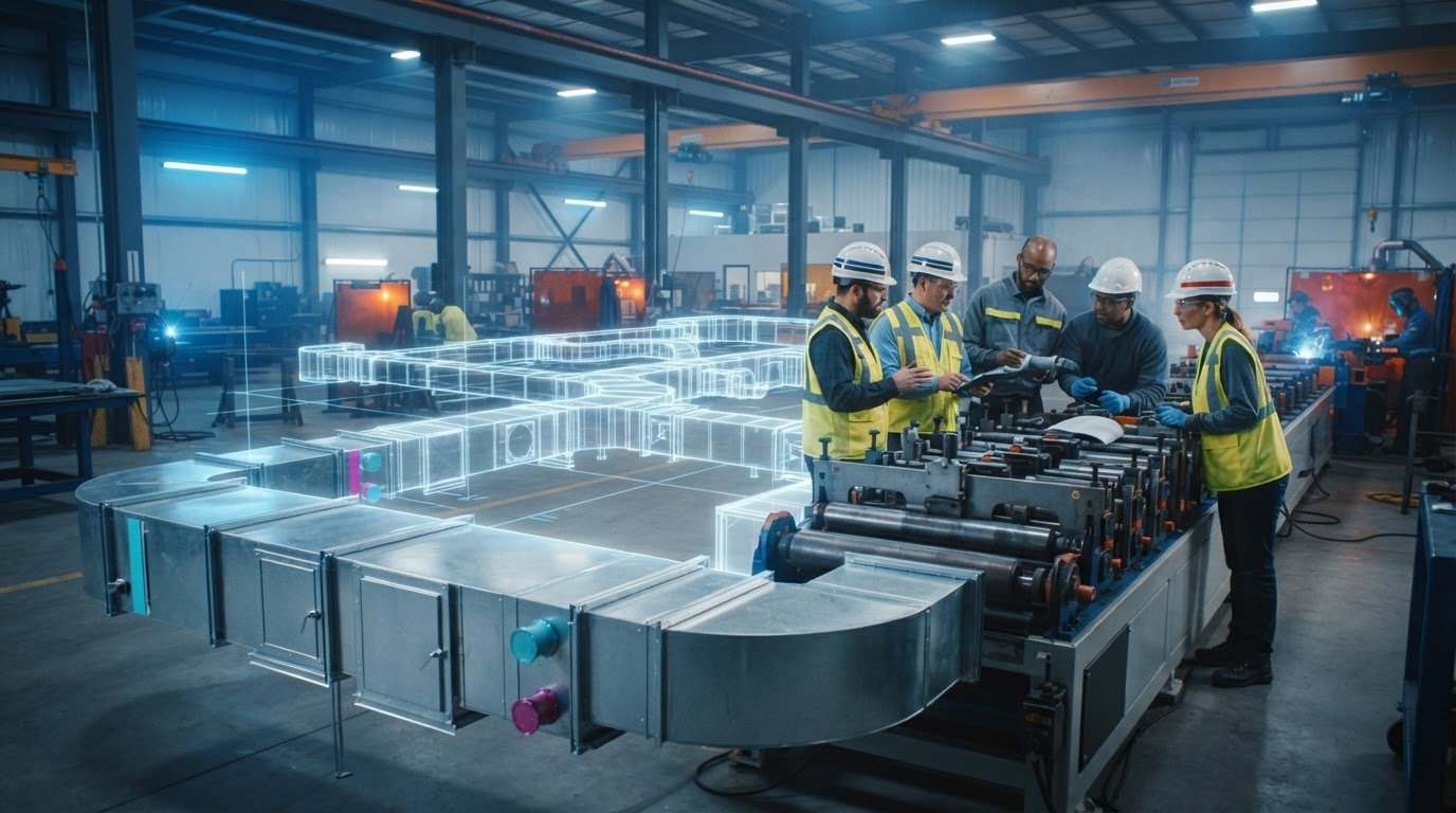
Effective bim ductwork coordination serves as the essential operating system for modern HVAC manufacturing. It's the bridge between a digital concept and a tangible product. In a traditional shop, a detailer might spend hours manually entering dimensions from a paper plan into a controller. This process is slow and invites human error. By establishing a direct "Digital-to-Physical" handshake, we eliminate these administrative delays. The data flows directly from the coordinated Revit model into the fabrication floor, ensuring the final product matches the design intent with surgical accuracy.
Success in this transition requires a structured approach, often outlined in a project-specific BIM Project Execution Planning Guide. This document defines how data transfers between the engineering team and the fab shop. When these protocols are followed, we achieve real-time production tracking. We know exactly where your coordinated duct is in the shop, from the moment the coil line starts to the second it’s loaded onto a truck for national shipping. This transparency allows for just-in-time delivery, keeping your jobsite installers productive and your project on schedule.
Automated Coil-Line Integration
High-volume production relies on the seamless import of .MAJ or .IFC files directly into fabrication software. When the machine knows the exact dimensions, gauge, and joint specifications from the model, rectangular duct production accelerates. This BIM-driven coil line duct fabrication utilizes nesting algorithms to optimize sheet metal yield. These algorithms arrange parts on the metal sheet to minimize scrap, significantly reducing material costs. It transforms the shop from a reactive environment into a precision-driven manufacturing facility.
Reducing Material Waste Through Precision
Precision modeling at LOD 400 results in fewer "scrap" pieces and virtually zero field fit-up errors. Coordinated models allow for custom laser cutting of specialized fittings that would otherwise require manual layout and cutting. By standardizing fittings within the model, we reduce production costs and speed up delivery times. Every piece of metal is accounted for before the machines even turn on. This level of precision is why we can promise a zero-clash installation. We don't just guess; we use the model to drive the machine, ensuring every component fits perfectly the first time.
Speed and Scalability: Why National Accounts Prioritize BIM-Ready Shops
National accounts and multi-site developers operate on tight schedules where predictability is essential. Managing multiple construction sites across the country requires a centralized digital strategy. Relying on local fabricators with varying capabilities leads to inconsistent quality and unexpected project delays. Advanced bim ductwork coordination allows national accounts to manage multiple project sites from a single digital source. This methodology ensures that a data center or healthcare facility built in one region matches the exact technical specifications of a facility built in another.
Centralized coordination enables rapid prototyping and on-demand part production. When design changes occur, the digital model updates globally, instantly reflecting on the factory floor. This tight integration reduces procurement lead times by leveraging single-source HVAC duct fabrication with national distribution. Contractors avoid the administrative delays of coordinating with multiple regional shops, resulting in faster fabrication-to-site timelines and predictable project delivery.
Standardizing Mechanical Components Nationwide
Consistency across a national portfolio requires a digital library of standardized parts. By establishing pre-coordinated Revit components, engineering teams eliminate the need to reinvent the layout for every new building. This standardization ensures that every duct run, flange specification, and hanger placement complies with SMACNA standards before fabrication. It streamlines the procurement process through coordinated digital submittals, allowing national accounts to lock in material pricing and accelerate the approval chain across all active projects.
Logistics and National Shipping of Coordinated Duct
Shipping uncoordinated duct is inefficient and expensive. Precision modeling allows for tighter nesting during packaging, maximizing truck space and reducing national shipping costs. Every fabricated section is labeled with a specific BIM spool number that corresponds directly to the installation drawings. This systematic approach supports a "Just-in-Time" delivery model, where ductwork arrives on pallets sorted by floor and zone. Installers spend their time assembling components rather than sorting through loose metal in a staging area.
If you need to scale your next multi-site rollout with guaranteed precision, our team is equipped to handle the logistics. You can partner with Velocity for national BIM coordination and fabrication services to streamline your entire procurement pipeline.
Velocity’s BIM-to-Fabrication Workflow: Precision at Scale
Velocity operates as the essential bridge between a digital file and a tangible product. We don't just consult on models; we own the machines that cut the metal. This "Authoritative Expert Operator" approach eliminates the typical administrative delays found when working with third-party BIM consultants who don't understand the factory floor. We integrate bim ductwork coordination directly with our automated coil-lines, ensuring every piece of rectangular or spiral duct meets the exact requirements of your VDC workflow. By owning both the model and the machine, we maintain total control over quality, speed, and delivery.
Our team acts as a partner who is ready to get to work immediately. We move your project from the initial digital concept to the final physical result with surgical precision. This integrated advantage means that the data driving our CNC plasma cutters and press brakes is the same data you've approved in the federated model. It's a streamlined process grounded in modern manufacturing reality rather than marketing hype. We provide the reliability you need to hit aggressive project milestones without the risk of field rework.
Partnering with Velocity for VDC Support
We partner with mechanical contractors to streamline the transition from design intent to physical installation. With over 50 years of combined industry experience, our team understands the practical realities of the jobsite. We don't just look for clashes; we look for optimization opportunities that reduce labor and material waste. Whether you're managing a high-volume commercial build or a complex healthcare facility, our coordination strategy focuses on zero-clash delivery. Contractors choose us because we handle everything from automated rectangular duct production to custom laser-cut fittings, providing a single-source solution for national project needs.
Getting Started: The Digital Intake Process
Our intake workflow is designed for speed and technical accuracy. We support industry-standard file formats, including .MAJ and .IFC, to ensure a seamless data transfer from your Revit environment. The process starts with a methodical technical review of your digital files to verify LOD requirements and system alignment. Once we reach a coordinated sign-off, the data moves immediately to our automated production lines. This transition from digital model to physical product happens in days, not weeks. We provide a transparent timeline that keeps your project moving forward without the typical bottlenecks of manual data entry.
If you're ready to eliminate field collisions and accelerate your timeline, it's time to get to work. You can submit your BIM files for a precision fabrication quote today and see how our integrated workflow drives results. We're ready to act as your tech-savvy partner, delivering precision at scale for your next national rollout.
Accelerate Your Next HVAC Project with Digital Precision
Transitioning from a generic design to a fully integrated digital-to-physical pipeline is no longer optional for high-volume commercial projects. Implementing rigorous bim ductwork coordination eliminates costly field collisions, slashes material waste, and ensures 100% fit-up on the jobsite. By moving to an LOD 400 workflow, mechanical contractors can transform complex duct installations into predictable assembly operations.
Velocity bridges the gap between your digital model and the factory floor. Backed by 50+ years of combined industry experience, we combine advanced BIM coordination with high-capacity automated coil-line production. We don't just fabricate; we optimize your data for maximum efficiency. Our nationwide shipping capabilities ensure standardized quality across your entire project portfolio, delivering sorted and labeled spools exactly when your field crew needs them. It's time to eliminate unexpected field rework. You can Get a Precision Fabrication Quote Based on Your BIM Model today and experience a streamlined, zero-clash workflow from digital concept to final delivery.
Frequently Asked Questions
What is the difference between BIM coordination and simple 3D modeling?
BIM coordination is a collaborative process that uses data-rich models to resolve spatial conflicts before fabrication begins. Simple 3D modeling is often just a visual representation without the metadata needed for clash detection. While a 3D model shows you how a system looks, coordination proves how it functions within the building's structural and MEP systems. It's the essential bridge from a digital concept to a fabrication-ready instruction set that drives automated production lines.
How does BIM ductwork coordination reduce total project costs?
Bim ductwork coordination reduces total costs by eliminating field rework, which research shows can cost thousands of dollars per clash. By resolving interferences in a digital environment, you avoid idle labor and emergency on-site modifications. It also optimizes material usage through precise nesting and reduces scrap waste. These efficiencies protect your profit margins and prevent the typical 9% budget increase associated with uncoordinated multi-trade installations. It turns the jobsite into a predictable assembly environment.
What software does Velocity use for BIM coordination and spooling?
We utilize the industry-standard Autodesk ecosystem to bridge the gap between design and the shop floor. Our workflow relies on Revit for detailed modeling and Navisworks Manage for comprehensive clash detection across all MEP trades. For the fabrication handshake, we use Fabrication CAMduct to generate .MAJ files. This software suite allows us to translate a coordinated LOD 400 model directly into CNC instructions for our automated coil-lines and laser cutting tables with surgical precision.
Can BIM coordination work for spiral duct as well as rectangular duct?
Yes. BIM coordination is essential for both spiral and rectangular duct systems. While rectangular duct often fills the main plenums, spiral and round duct require precise coordination to navigate tight ceiling spaces and structural obstacles. Our digital workflow handles complex fittings and transitions for all duct types. This ensures that every piece of spiral pipe and every rectangular fitting arrives on site with guaranteed spatial accuracy, regardless of the system's geometry or static pressure requirements.
How much time should I allocate for the BIM coordination phase?
Coordination timelines vary based on project scale and system density. Generally, you should allocate four to eight weeks for the full VDC process before fabrication begins. This window allows for multiple clash detection cycles and sign-off from all trades. Investing this time upfront prevents weeks of delays in the field. Our integrated approach accelerates this timeline by moving directly from a coordinated digital sign-off to our high-capacity automated production lines, keeping your project moving at speed.
Does BIM coordination eliminate the need for field measurements?
Coordination significantly reduces the need for field measurements but doesn't replace initial structural verification. We use the model as the single source of truth, but verifying "as-built" conditions ensures the digital file reflects the actual jobsite reality. Once verified, the need for installers to measure and cut in the field is virtually eliminated. This shift allows your crew to focus on high-speed installation rather than custom fabrication, transforming the site into an efficient assembly operation.
How do spool drawings improve the installation process for field crews?
Spool drawings act as a granular assembly manual for your field crew. Each drawing breaks down complex duct runs into manageable, shippable sections labeled with unique spool numbers. These numbers correspond directly to the physical labels on our fabricated ductwork. Instead of guessing where a piece fits, installers follow a clear digital map. This systematic approach reduces sorting time and ensures that the right parts are delivered to the right floor for immediate, zero-clash installation.