Laser Cutting Tolerances: 2026 Specification Guide
Over-specifying a part is just as dangerous as under-engineering it. Requesting a ±0.0005 tolerance when your assembly only needs ±0.005 won't make your product better. It just makes your production slower and your margins thinner. Mastering laser cutting tolerances for engineers is about more than hitting a target on a screen; it's about bridging the gap from digital design to physical reality. We know the frustration of parts that won't seat during assembly. We've seen costs spiral from unrealistic precision demands on thick plate steel. You need a partner who understands how the laser behaves when it hits the metal.
Precision is a collaborative output of engineering intent and operator expertise. You want parts that fit the first time without paying for unnecessary accuracy. This guide provides the technical benchmarks you need to navigate the 2026 manufacturing landscape. We'll define achievable tolerance bands for steel and aluminum, explain how material thickness impacts your kerf, and show you how to optimize your DFM for national-scale production. From initial digital concepts to the final physical result, you'll learn to balance high-speed automation with the surgical accuracy your project demands.
Key Takeaways
- Identify the specific ISO 9013 quality grades that define thermal cutting standards to set realistic expectations for your next project.
- Master the technical variables of laser cutting tolerances for engineers by accounting for kerf width and thermal expansion before your file hits the machine.
- Use our thickness-specific comparison charts to determine when a ±0.002 tolerance is necessary and when standard bands will save you time and money.
- Implement DFM best practices, like the 1:1 hole-to-thickness ratio, to ensure structural integrity and clean edges across high-volume production runs.
- Learn how BIM coordination and automated fabrication lines eliminate assembly errors by standardizing quality from the digital concept to the final delivery.
Defining Laser Cutting Tolerances: Standards and Terminology
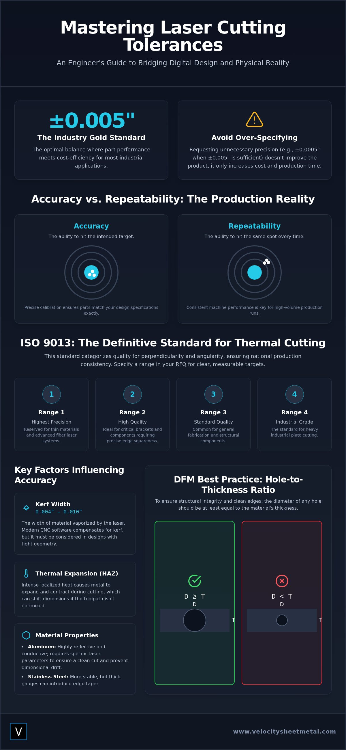
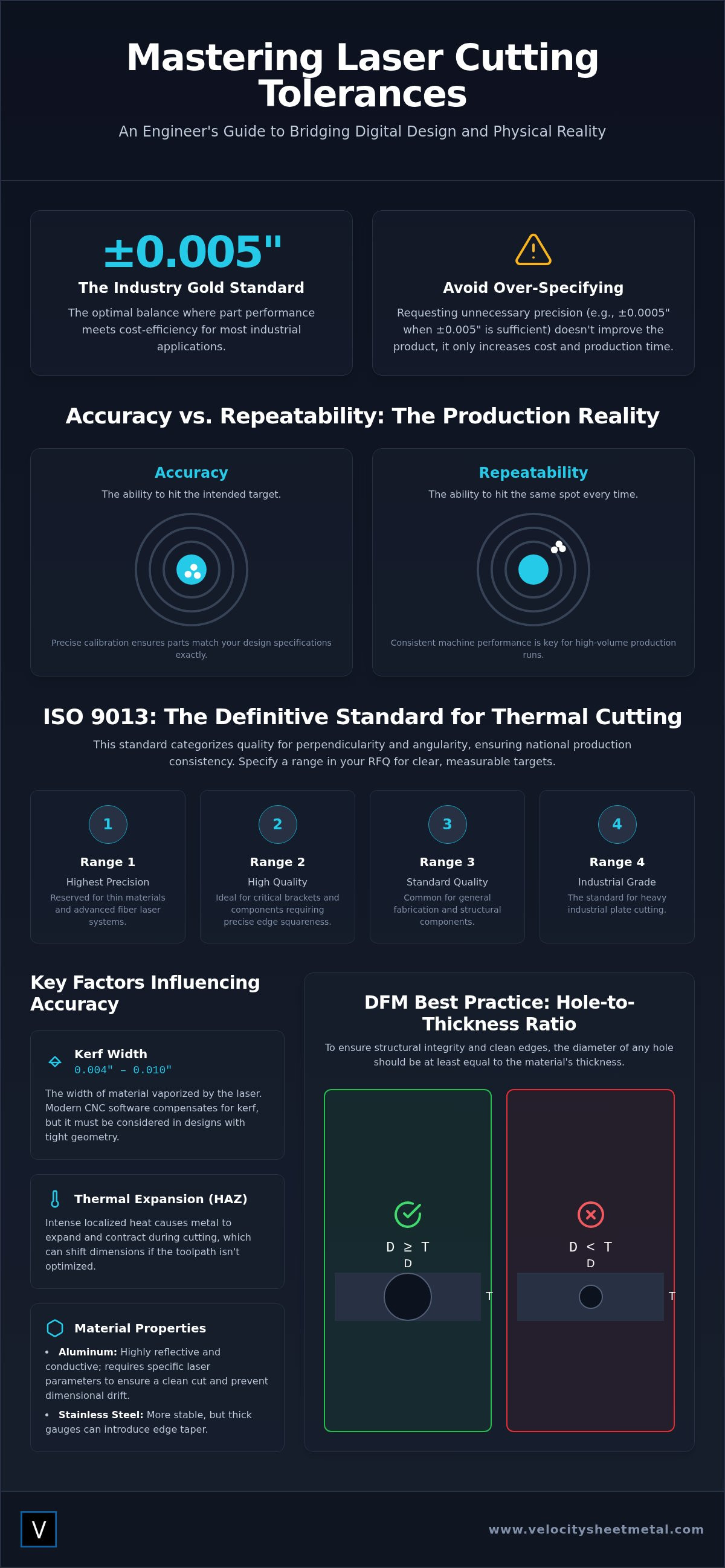
In industrial fabrication, ±0.005" is the gold standard. It's the sweet spot where part performance meets cost-efficiency. For many, laser cutting tolerances for engineers are often misunderstood as mere machine settings. In reality, they're the result of a physical interaction between light and matter. Laser beam machining processes must account for material movement, beam divergence, and thermal stress. If you rely on general tolerances like ISO 2768, you're likely ignoring the unique variables of sheet metal, such as internal stresses and gauge variations. Those general standards are built for subtractive machining, not the thermal dynamics of a high-power fiber laser.
Relying on the wrong terminology leads to expensive mistakes. We see it often: an engineer requests a tolerance tighter than the material's own thickness variation. It's a recipe for rejected parts and wasted budget. Achieving a repeatable ±0.005" benchmark requires an operator who understands the machine's limits and the metal's temperament. From thin gauge aluminum to heavy plate steel, the goal is always the same. You need a part that fits the assembly without requiring secondary operations or manual filing.
ISO 9013: The Thermal Cutting Benchmark
ISO 9013 is the definitive standard for thermal cutting. It categorizes quality grades for perpendicularity and angularity across four distinct ranges. Range 1 represents the highest precision, typically reserved for thin materials and advanced fiber systems. Range 4 is the standard for heavy industrial plate. When you specify these grades in your RFQ, you ensure national production consistency. It moves the conversation from "make it fit" to "make it to spec." Specifying ISO 9013 Range 2 for a critical bracket, for example, gives the fabricator a clear, measurable target for edge squareness that mechanical machining standards simply can't define.
Accuracy vs. Repeatability: The Production Reality
A machine can be precise but inaccurate. Precision is about hitting the same spot every time. Accuracy is about hitting the intended spot. For national accounts, long-run consistency depends on rigorous machine maintenance and calibration. If a laser head isn't calibrated, every part in a 1,000-unit run will be identically wrong. This is where the "Expert Operator" persona becomes vital. They don't just hit "start"; they monitor the beam's focus and the gas pressure to maintain the cut quality from the first sheet to the last. Positional accuracy refers to the machine's ability to reach a precise coordinate on the cutting bed, whereas repeatability measures the consistency of the laser returning to that same point over thousands of cycles.
Factors Influencing Dimensional Accuracy in Metal Fabrication
Accuracy in laser cutting isn't a fixed setting on a control panel. It's a dynamic result of material physics and machine calibration. To master laser cutting tolerances for engineers, you must account for the kerf, the heat-affected zone (HAZ), and the specific behavior of the alloy under the beam. High-power lasers generate intense localized heat. This heat causes the metal to expand and contract during the process. If the cutting path isn't optimized, this thermal movement shifts dimensions before the part even leaves the nest.
The Kerf Factor: Designing for the Beam
The kerf is the width of material removed by the laser beam during the cut. In 2026, fiber lasers typically produce a kerf between 0.004" and 0.010" depending on the material and thickness. While modern CNC software automatically compensates for this width, engineers should account for it in tight geometries and interlocking tabs. Lead-ins and lead-outs are critical here. If placed incorrectly, the entry point of the laser creates a small divot. This tiny imperfection can throw off internal feature tolerances by several thousandths, which is a dealbreaker for high-precision OEM components.
Material Science: Aluminum vs. Stainless vs. Carbon Steel
Different metals react uniquely to thermal stress. Aluminum is highly reflective. It requires specialized fiber laser parameters to prevent back-reflection and ensure a clean cut. It also conducts heat quickly. This rapid conduction often leads to dimensional drift in small, intricate parts. Stainless steel offers more stability, but thick gauges introduce the risk of edge taper. Safety and precision go hand-in-hand. Our facility operates under strict OSHA Laser Hazard Standards to maintain a controlled environment where machine performance never wavers.
Assist gases dictate the final edge quality and dimensional stability. Nitrogen is the standard for stainless and aluminum. It cools the cut and prevents oxidation, leaving a weld-ready edge. Oxygen is often used for thicker carbon steel to add thermal energy, though it increases the HAZ. As material thickness increases, the relationship between gauge and tolerance drift becomes linear. A 26ga sheet holds a much tighter tolerance than a 1/2" plate. The thicker the metal, the more the beam scatters and the more heat the part absorbs. Managing these variables is essential for large-format sheets used in custom laser cutting for HVAC ductwork and industrial transitions.
Tolerance Comparison Chart: Material and Thickness
Tolerances are a moving target. They shift as the gauge increases. For most industrial applications, a standard tolerance of ±0.005" is the industry benchmark. However, chasing a ±0.002" tolerance comes with a cost premium. It requires slower cutting speeds and more frequent nozzle changes. Understanding laser cutting tolerances for engineers means knowing when to pay for precision and when to accept standard bands. We've seen projects stall because an engineer specified aerospace-level accuracy for a simple duct flange. It's an expensive mistake that doesn't improve the final product.
Consistency is key for national accounts. Our automated coil-line production ensures that rectangular duct components meet standardized quality levels every time. This automation removes the human error often found in manual fabrication. But remember, the laser cut is only the first step. If your part requires CNC press brake bending, you must account for stacking tolerances. A perfect laser cut can still result in a failed assembly if the bend allowance isn't calculated correctly. The ISO 9013 standard for thermal cutting provides the framework for these measurements, but real-world variables like material springback always play a role.
Thin Gauge Precision (Under 0.125")
Precision shines in thin materials. From 26ga to 10ga, fiber lasers excel at intricate internal geometries. We can maintain tight tolerances for electronic enclosures and brackets where every millimeter counts. Utilizing precision laser cutting services allows for interlocking tabs and slots that snap together with surgical accuracy. This reduces the need for heavy welding or complex jigging. In these gauges, the heat-affected zone is minimal, allowing for clean edges that require zero post-processing before assembly.
Heavy Plate Considerations (Over 0.250")
Thickness changes the physics of the cut. As you move into 0.250" plate and beyond, edge taper becomes a factor. The beam naturally scatters as it penetrates deeper into the metal. This creates a slight angle on the cut edge, which can impact how structural OEM components fit together. To maintain dimensional accuracy, we adjust assist gas pressure and cutting speed. There's a direct trade-off here. Faster speeds might lower the cost per part, but they increase the risk of dimensional drift. For heavy-duty duct flanges and structural supports, Range 3 or 4 of the ISO standard is typically the most cost-effective path.
Design for Manufacturability (DFM): Engineering Best Practices
Precision is worthless if the part is unmanufacturable. Effective DFM bridges the gap between a clean CAD file and a repeatable physical component. When analyzing laser cutting tolerances for engineers, the most critical rule is the 1:1 hole-to-thickness ratio. If you design a 0.125" hole in 0.250" plate, the laser will dwell too long. This creates excessive dross and edge distortion. Sticking to a 1:1 ratio ensures the beam moves fast enough to maintain dimensional integrity across the entire run. It's the baseline for industrial reliability.
Tab and slot designs leverage laser precision to eliminate expensive welding fixtures. By designing self-fixturing parts, you reduce assembly labor and prevent alignment errors. This is particularly effective for complex OEM enclosures where stacking tolerances can otherwise ruin a project. If each component is at the edge of its tolerance band, the final assembly will fail. Smart DFM accounts for this cumulative error at the design stage. It's about ensuring that the sum of your parts doesn't exceed the limits of your assembly.
The BIM-to-Machine Workflow
Digital coordination is the backbone of modern fabrication. Using BIM clash detection for HVAC fabrication allows us to catch interference issues before the first sheet is cut. We translate complex spool drawings into precision-cut flat patterns that fit perfectly in the field. This workflow doesn't just save time; it maximizes nesting optimization to reduce material waste. You get higher part accuracy and lower production costs through better digital planning. It's a seamless transition from a digital concept to a tangible, high-performance product.
The DFM Checklist for Engineers
To optimize your designs for national-scale production, follow these core principles:
- Avoid sharp internal corners. Use a minimum radius of 50 percent of the material thickness to reduce stress concentrations and heat buildup.
- Distinguish between critical and non-critical dimensions. Over-specifying non-mating surfaces adds unnecessary cost without improving performance.
- Account for the Heat Affected Zone (HAZ). Keep delicate features away from heavy cut lines to prevent warping during the thermal process.
Designing with stacking tolerances in mind is vital for multi-component HVAC systems. Don't let cumulative errors stall your project or increase field labor. Ready to move from CAD to production with surgical precision? Send us your files for a custom laser cutting technical review today.
Velocity Sheet Metal: National Precision and Scalability
Execution is where engineering value is realized or lost. At Velocity Sheet Metal, we act as the essential bridge between your digital file and a tangible, high-performance product. We've spent 50+ years refining the balance between industrial speed and surgical accuracy. Standardizing laser cutting tolerances for engineers across national accounts isn't just about the machine; it's about a controlled, repeatable process. Whether you're managing a single high-spec build or a multi-state rollout, our facility ensures every part meets the same rigorous benchmarks.
Our operation is built on modern manufacturing reality. We've replaced traditional administrative delays with automated technology and straight-talk logistics. From the initial BIM coordination to the final logistics of delivery, our workflow moves with surgical precision. We don't just cut metal; we provide the technical capability to scale your production without sacrificing the integrity of your design. This national focus allows us to bring high-end engineering standards to every job site in the US, ensuring consistency across every project in your portfolio.
Automated Reliability for Mechanical Contractors
Automation is the only way to eliminate human error in high-volume production. Our coil-line automated rectangular duct production delivers standardized quality that manual shops can't match. This level of precision is critical for HVAC duct fabrication for mechanical contractors who need parts to fit perfectly the first time. Beyond standard ductwork, we provide fast turnaround times for custom curb adapters and transition fittings. We move your project from CAD to the field with zero friction, keeping your installation crews moving at full speed.
On-Demand Part Production for OEMs
Scaling a prototype to national distribution requires a partner who understands the physics of the metal. We specialize in on-demand part production that maintains tight tolerances across thousands of cycles. Our CNC press brake services for OEMs complement our laser precision, allowing us to deliver complex, formed components that are ready for assembly. We manage the technical review and nesting optimization so you can focus on your core business. It's a reliable, tech-savvy partnership obsessed with detail and delivery, moving your digital concept to a physical result with surgical efficiency.
Precision Meets Scalability: Your Path to 2026 Manufacturing Standards
Mastering laser cutting tolerances for engineers is no longer just a technical requirement; it's a competitive advantage. You now have the benchmarks to distinguish between standard ±0.005" bands and the high-precision demands of intricate OEM components. By aligning your DFM with the physical realities of kerf and thermal expansion, you eliminate the assembly failures that stall complex projects. Precision is not just a machine setting. It's the result of combining engineering intent with an operator's expertise and modern automation.
Velocity Sheet Metal acts as the essential bridge from your digital concept to a physical result. Our BIM-integrated fabrication workflow ensures that every part is standard-compliant and field-ready. We utilize a high-volume automated production capacity to maintain consistency across every project in your national portfolio. Whether you need custom ductwork or precision-cut components, we deliver surgical accuracy with industrial speed. We understand the stakes of your project and the value of your time.
Ready to streamline your production and reduce manufacturing costs? Request a Precision Quote for National Shipping and see how our expertise can power your next project. Let's get to work.
Frequently Asked Questions
What is the standard laser cutting tolerance for 1/4-inch carbon steel?
The standard tolerance for 1/4-inch carbon steel typically ranges between ±0.005 and ±0.010 inches. While advanced fiber lasers can hit tighter targets, the material thickness increases the beam's dwell time and heat absorption. For most industrial applications, these laser cutting tolerances for engineers represent a reliable baseline that ensures assembly fit without driving up production costs. We recommend following ISO 9013 Range 2 or 3 for consistent results on heavy plate.
How does laser cutting tolerance compare to waterjet or plasma cutting?
Laser cutting offers a middle ground of high speed and superior precision compared to plasma, which typically holds ±0.020 to ±0.030 inches. Waterjet can achieve tighter tolerances on extremely thick materials without creating a heat-affected zone, but it operates at a much slower speed. For gauges under 1/2 inch, laser is the industry standard for balancing dimensional accuracy with high-volume throughput. It provides a cleaner edge and more consistent repeatability for national OEM accounts.
Can laser cutting achieve a ±0.001-inch tolerance?
Achieving a ±0.001-inch tolerance is generally not feasible with industrial fiber laser systems. Most high-end machines cap their repeatable precision at ±0.002 to ±0.003 inches under optimal conditions. Attempting to specify ±0.001 often leads to rejected parts and unnecessary secondary machining costs. If your project requires micron-level accuracy, you should consider CNC milling or grinding as a post-processing step to meet those specific engineering requirements after the initial laser cut.
How does material thickness affect the 'kerf' and final part dimensions?
Material thickness has a linear relationship with kerf width and dimensional stability. As the gauge increases, the laser must move slower, which widens the kerf from approximately 0.004 inches on thin sheet to 0.012 inches on thick plate. This added heat increases the risk of thermal expansion during the cut. Our automated systems compensate for these variables in the software, but engineers must account for the wider kerf when designing tight-fitting interlocking components or small internal features.
What is the minimum hole diameter I can specify for laser-cut parts?
The golden rule for minimum hole diameter is a 1:1 ratio relative to the material thickness. For example, a 1/4-inch plate should have holes no smaller than 0.250 inches in diameter. Specifying smaller holes causes the laser to dwell too long in a concentrated area, leading to dross buildup and distorted geometries. Maintaining this ratio ensures clean, round holes that meet laser cutting tolerances for engineers without requiring manual reaming or secondary drilling operations.
Does laser cutting cause part warping due to heat?
Thermal distortion is a reality in laser cutting, especially on large-format sheets or parts with dense feature patterns. The heat-affected zone (HAZ) causes localized expansion, which can lead to warping if the cutting path isn't optimized. We mitigate this through strategic nesting and cooling paths that allow heat to dissipate between cuts. Using Nitrogen as an assist gas also helps cool the material faster than Oxygen, maintaining the structural flatness required for precision HVAC ductwork.
How do I specify tolerances in my CAD files for the best results?
The best way to specify tolerances is to define critical mating surfaces while leaving non-critical dimensions to standard industrial bands. Avoid over-specifying every dimension in your CAD file, as this creates administrative delays and inflates pricing. Instead, reference ISO 9013 quality grades or provide a separate PDF spec sheet that highlights specific holes or edges requiring high precision. This allows our expert operators to focus calibration efforts where they actually impact your assembly's performance.
Why is Nitrogen used as an assist gas for precision stainless steel cutting?
Nitrogen is the preferred assist gas for stainless steel because it acts as an inert cooling agent. Unlike Oxygen, which creates an exothermic reaction to add heat, Nitrogen simply blows away the molten metal. This prevents oxidation and discoloration on the cut edge, resulting in a clean finish that is ready for immediate welding or painting. It also allows for higher cutting speeds on thin gauges, ensuring the high-volume reliability needed for national account standardization.