Design for Manufacturability (DFM) for Sheet Metal: The 2026 Technical Guide

With hot-rolled coil steel prices hovering around $1,170 per short ton in mid-2026, a single unmanufacturable design choice isn't just a technical error; it's a direct hit to your bottom line. You've likely dealt with the frustration of parts that fail during the bending process or lead times that stretch weeks beyond the initial estimate because of minor geometry issues. It's a common pain point for engineers who need to bridge the gap between a digital model and a physical part without racking up massive scrap rates.
This technical guide will help you master design for manufacturability sheet metal principles to eliminate production bottlenecks and reduce per-part costs. You'll learn how to align your CAD geometry with the specific constraints of CNC press brakes and automated punching systems. We're breaking down the essential rules for bend deductions, hole placement, and material selection to ensure your transition from BIM coordination to production is seamless and precise. By the end of this article, you'll have the technical roadmap needed to hit your tolerances every time while keeping your projects on schedule.
Key Takeaways
- Front-load your engineering decisions to lock in lower production costs and prevent expensive scrap before manufacturing begins.
- Master the specific hole-to-edge distances and flange requirements essential for effective design for manufacturability sheet metal across various material gauges.
- Use BIM coordination and spool drawings to eliminate fabrication errors and material waste before the metal hits the coil-line.
- Identify the critical bending constraints for heavy-duty alloys and lightweight ducting to ensure your parts don't fail at the press brake.
- Transition quickly from a single CAD file to national-scale OEM production by standardizing your technical data package for high-volume fabrication.
Understanding Design for Manufacturability (DFM) in Sheet Metal Fabrication
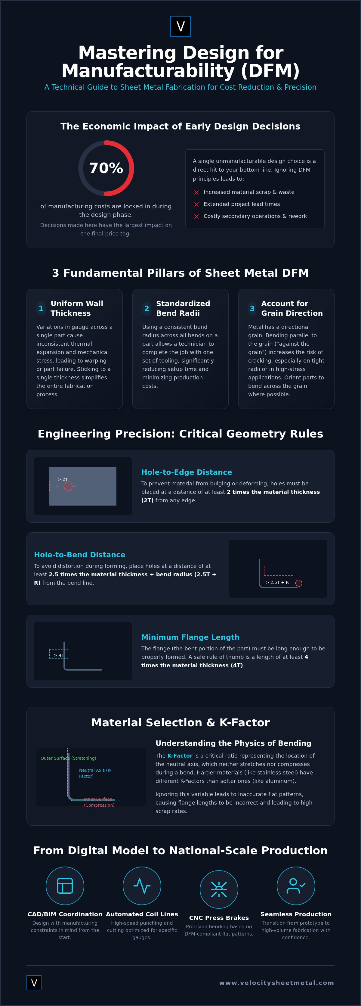
Design for manufacturability (DFM) is the engineering practice of designing parts specifically for ease of manufacturing. In the world of precision fabrication, it's the difference between a profitable run and a bin full of scrap. Industry data consistently shows that 70% of manufacturing costs are locked in during the design phase. By the time a digital file reaches the shop floor, your ability to influence the final price tag has largely evaporated. The primary objective is to strip away unnecessary complexity while reinforcing structural integrity. This ensures that every part moves through precision metal punching and CNC bending stations without manual intervention or rework.
The relationship between the digital concept and the physical result is direct. If a design ignores the mechanical limits of the equipment, the project will face delays. Precision metal punching and bending are the core of the process, but they only work efficiently when the geometry is optimized for the machine's path. A design that looks perfect in a CAD environment might be impossible to grip on a press brake or too thin to survive a high-speed punch. DFM acts as the essential bridge that translates a digital vision into a tangible, high-quality product.
The Economic Impact of DFM
Effective DFM practices directly target the hidden costs of secondary operations. When a design is optimized, you eliminate the need for manual deburring, complex jigging, or multiple setup changes. For HVAC contractors, this translates to faster lead times and lower overhead. Every minute saved at the automated coil line or the laser cutter is a minute saved on the final installation schedule. High-volume production demands a "get it right the first time" approach to maintain slim margins. In high-volume production, DFM cost-efficiency is achieved by aligning digital geometry with the specific physical constraints of automated machinery.
Core Principles of Sheet Metal Engineering
Successful design for manufacturability sheet metal hinges on three fundamental pillars. First, maintain uniform wall thickness. Variations in gauge across a single part can cause inconsistent thermal expansion and mechanical stress, leading to warping or part failure. Second, standardize your bend radii. Using a single radius across all bends allows a technician to complete the job with one set of shop tooling, significantly reducing setup time. Finally, account for grain direction. Metal has a grain similar to wood; bending against the grain increases the risk of cracking in high-stress applications. Following these rules ensures that parts remain consistent from the first prototype to the ten-thousandth production unit.
Material Selection and Gauge Constraints for Optimized Production
Material selection is the foundation of design for manufacturability sheet metal. It's not just a matter of cost; it's a matter of physics. Steel, aluminum, and stainless steel each respond differently to the mechanical stress of a punch or the high tonnage of a CNC press brake. For instance, aluminum usage is expected to grow by 15% by 2028, largely driven by the electric vehicle market and lightweighting trends. This shift requires engineers to account for aluminum's specific springback characteristics, which differ significantly from the predictable behavior of carbon steel. If you design for steel but fabricate in aluminum without adjusting your tolerances, your parts won't fit.
To produce an accurate flat pattern, you must calculate the K-Factor. This ratio represents the location of the neutral axis relative to the material thickness. During a bend, the inner surface compresses and the outer surface stretches; the neutral axis is where no change in length occurs. Harder materials like 304 stainless steel have different K-Factors than soft galvanized steel. Ignoring these variables leads to flange lengths that are off by fractions of an inch, causing assembly failures and high scrap rates. With hot-rolled coil steel prices at approximately $1,170 per short ton in mid-2026, these errors are too expensive to ignore.
Choosing the Right Gauge for the Application
Automated coil lines are optimized for specific gauge ranges to maximize speed and precision. For rectangular duct and HVAC applications, we typically operate between 26 and 18 gauge. When your project moves into industrial mounting brackets or structural components, you'll likely specify heavy gauge plate, such as 10 gauge or thicker. Heavier gauges require larger bend radii to prevent cracking at the heel of the bend. Balancing structural requirements with weight is essential for shipping efficiency and material cost control. If your design requires complex geometries in thicker materials, precision laser cutting services provide the accuracy needed for tight tolerances.
Surface Finishes and Post-Processing
Post-processing can change your part's final dimensions. Galvanized steel is the industry standard for corrosion resistance in ductwork, but it doesn't require the same dimensional allowances as powder-coated parts. Powder coating typically adds between 0.003 and 0.005 inches to each surface. If your CAD model doesn't account for this buildup, your tabs and slots will be too tight for assembly. Always design with the final finish in mind to ensure a seamless fit. If you're ready to move from digital concept to physical part, partner with our fabrication experts to verify your material specs before production starts.
Engineering Precision Metal Punching and Bending Geometry
Precision requires boundaries. When you move from a digital model to the shop floor, the physical limits of the punch and die take over. A common failure in design for manufacturability sheet metal is placing holes too close to a bend line or an edge. If the distance between a hole and the edge is less than 1.5 times the material thickness, the metal will bulge or tear during the strike. This deformation ruins the aesthetic and compromises structural integrity. Similarly, your hole diameter must never be smaller than the material thickness. Attempting to punch a sub-thickness hole puts excessive stress on the tooling, leading to premature tool wear or catastrophic failure during high-speed production.
Bending geometry is equally unforgiving. To achieve a clean, accurate angle, the CNC press brake must have enough material to grip. If your flange length is too short, the part will slip into the die, resulting in an inaccurate bend and a dangerous work environment. A reliable rule of thumb is to maintain a minimum flange length of at least four times the material thickness plus the bend radius. To prevent tearing at the corners where two bends meet, you must design relief notches. These small cutouts allow the material to move freely, ensuring the corner remains crisp and the structural load is distributed evenly across the part.
Standardizing Bend Radii
Consistency accelerates the workflow. Every time a technician changes a tool to accommodate a different bend radius, the production line stops. By using a single radius across your entire design, you allow for a continuous run with zero downtime. This is particularly critical when designing custom mounting brackets for industrial equipment, where repeatability is the priority. Your design must also account for springback, which is the tendency of metal to partially return to its original shape after the pressure is released. Precision shops over-bend the material based on its specific hardness and thickness to hit the exact angle required by your technical specifications.
Precision Punching Clearances
Success in automated punching depends on the gap between the punch and the die. Proper die clearance, typically 10% to 15% of the material thickness, ensures a clean shear and prevents "slug pulling." Slug pulling occurs when the waste material sticks to the punch and is lifted back onto the sheet, causing surface damage or machine jams. For high-volume OEM orders, automated punching systems deliver parts with surgical precision at speeds that manual processes can't match. This digital-to-physical integration reduces lead times from weeks to days, keeping your supply chain moving without administrative delays.

Leveraging BIM and Automation to Eliminate Fabrication Waste
Digital precision eliminates physical waste. Building Information Modeling (BIM) is no longer a luxury for complex projects; it's the core of modern design for manufacturability sheet metal. When you integrate DFM rules directly into your BIM environment, the software acts as a gatekeeper. It prevents unmanufacturable geometry from ever reaching the shop floor. By identifying clashes between ductwork and structural steel in the virtual model, you avoid the high scrap rates and emergency field fixes that derail project budgets. Every pound of metal saved in the model is a pound of profit protected in production.
Mechanical spooling is the essential bridge in this workflow. It takes a coordinated 3D model and breaks it down into individual, shop-ready parts or "spools." These files carry all the necessary metadata for production, from material gauge to specific notch locations. This seamless data transfer ensures that the precision metal punching and bending instructions are exactly what the engineer intended. Automated coil lines handle standardized DFM inputs by instantly adjusting feed rates and notch depth based on the digital file's specifications. This eliminates manual data entry and the human error that often leads to part failure during assembly.
BIM-to-Machine Workflows
The speed of commercial construction demands a "digital-to-physical" approach. Utilizing BIM for sheet metal fabrication allows HVAC contractors to visualize the entire system before a single piece of metal is cut. This foresight reduces field collisions through accurate spool drawings that reflect real-world machine constraints. For national accounts and large-scale OEMs, this level of automation ensures that a part manufactured in July is identical to one produced in December. Consistency is the foundation of scalability. To see how digital coordination can accelerate your next project, get a technical review from our BIM experts today.
Standardizing HVAC Ductwork
High-volume efficiency requires standardization. When you are designing for coil line duct fabrication, optimizing rectangular duct dimensions is your primary lever for speed. Automated lines are built for throughput; they thrive on predictable geometries and consistent material types. By aligning your duct designs with automated production speeds, you reduce the time each part spends on the line. This doesn't just lower your per-part cost; it drastically shortens your total lead time. The result is a leaner supply chain and a faster transition from digital concept to final installation.
Transitioning from CAD to National-Scale Production
Scaling from a single prototype to a national OEM production run requires more than just a clean CAD file. It demands a robust technical data package that eliminates ambiguity. Your package should include 3D STEP files, accurate flat patterns, and clear material specifications. When design for manufacturability sheet metal principles are applied correctly, you ensure that every part produced for a national account meets the same rigorous quality standards, regardless of the job site location. On-demand production capabilities allow you to maintain aggressive construction timelines by receiving parts exactly when the installation crew is ready for them.
The transition from digital design to physical reality is where many projects face unexpected delays. Standardizing your quality requirements is essential for national accounts with multiple job sites. It ensures that the rectangular duct or custom brackets you receive in one region are identical to those delivered across the country. This level of predictability is the foundation of modern industrial scaling. It allows for a seamless workflow that moves from the initial BIM model to high-speed fabrication without manual intervention or redesigns.
Logistics and National Shipping
Designing for nested shipping is a primary lever for reducing freight costs. If parts can be shipped flat and assembled on-site, you maximize truck space and lower your overhead. Packaging is equally critical; precision components require specific bracing to prevent edge damage during transit. Velocity Sheet Metal maintains nationwide shipping capabilities, ensuring that high-volume ductwork and custom fabricated parts reach your facility or job site with surgical timing. We prioritize logistics as much as fabrication to keep your project on schedule.
Partnering with an Expert Fabricator
Partnering with a fabricator early in the design phase is the most effective way to lock in efficiency. This process, known as Early Supplier Involvement (ESI), allows us to spot potential failures before you commit to a large-scale order. Implementing design for manufacturability sheet metal strategies during these early reviews prevents costly manufacturing errors that only appear at high volumes. A "straight-talk" technical review cuts through the administrative noise and focuses on the physical reality of the shop floor. Contact Velocity for a technical review of your next HVAC or OEM project to ensure your design is optimized for speed, precision, and national distribution.
Future-Proof Your Metal Fabrication Strategy
Mastering design for manufacturability sheet metal is about more than just avoiding errors; it's about building a scalable, high-velocity supply chain. You've seen how aligning geometry with CNC press brake limits and utilizing BIM coordination eliminates the administrative delays that stall projects. From the initial digital spool drawing to the final automated coil-line strike, every step must be intentional. This technical alignment ensures your parts are produced with surgical precision and delivered to your job site without the hidden costs of scrap or rework.
Velocity Sheet Metal acts as the essential bridge between your CAD files and a tangible, high-quality product. We bring 50+ years of combined industry experience and a BIM-integrated fabrication shop to every order. Our automated coil-line technology is built for speed and repeatability on a national scale. Don't let unmanufacturable designs slow down your construction timeline. Get a Precision Fabrication Quote for Your National Project today. We're ready to get to work on your next precision fabrication challenge.
Frequently Asked Questions
What is the most common mistake in sheet metal design for manufacturability?
Placing holes or slots too close to a bend line is the most frequent error we see on the shop floor. When a feature is located within the bend's deformation zone, the material will stretch and pull the hole into an oval shape. To maintain a successful design for manufacturability sheet metal workflow, keep all features at least three times the material thickness away from the bend radius.
How does material thickness affect the minimum bend radius?
The minimum bend radius is directly proportional to the material thickness, typically following a 1-to-1 ratio (1T). Attempting to bend a part with a radius smaller than the material thickness often leads to cracking on the outer surface or "orange peeling" in the grain. For harder alloys or thicker plates, you may need to increase this to 2T or 3T to ensure structural integrity and prevent part failure during the CNC bending process.
Why is hole-to-edge distance critical in precision metal punching?
Maintaining proper hole-to-edge distance prevents the material from bulging or tearing during the high-pressure punching strike. The rule of thumb is to keep the distance between the hole and the edge at least 1.5 to 2 times the material thickness. This ensures the web of material remains strong enough to withstand the shear forces of the punch without deforming the surrounding geometry.
Can BIM software automatically check for DFM compliance?
Modern BIM platforms like Revit 2027 and specialized fabrication add-ons can automate many DFM checks before you export your spool drawings. These tools flag physical clashes and identify unmanufacturable geometries, such as flanges that are too short for a CNC press brake to grip. Integrating these checks into your digital workflow reduces the need for manual technical reviews and prevents costly redesigns after the metal has been ordered.
What are the advantages of automated coil lines for rectangular duct?
Automated coil lines deliver unmatched speed and repeatability for high-volume rectangular duct production. These systems handle the uncoiling, leveling, and notching in a single continuous process, which eliminates the variability of manual fabrication. This automation is essential for national accounts that require consistent quality across thousands of feet of ductwork while maintaining tight construction schedules.
How do you account for springback in CNC press brake bending?
Springback is managed by over-bending the material past the target angle so it "springs" back to the correct position once the pressure is released. Our CNC press brakes use advanced controllers to calculate this offset based on the material's specific yield strength and K-Factor. Precision is maintained by adjusting the bend depth in real-time, ensuring that every angle remains within the specified tolerance regardless of material variations.
What information should be included in a technical data package for fabrication?
A complete technical data package must include 3D STEP files, flat patterns in DXF format, and a detailed PDF with critical dimensions and tolerances. You should also clearly specify the material grade, gauge, and any required surface finishes like galvanization or powder coating. Providing this data upfront allows our team to perform a "straight-talk" technical review and move your project directly into the production queue.
Does DFM differ significantly between aluminum and stainless steel?
Yes, the design for manufacturability sheet metal rules change based on the material's ductility and hardness. Aluminum is more prone to cracking and requires larger bend radii than carbon steel, while stainless steel's high yield strength demands significantly higher tonnage and specialized tooling. Ignoring these material-specific constraints during the design phase will lead to unexpected part failure or excessive tool wear during the punching and bending cycles.