Custom HVAC Transition Fittings: Design for Better Airflow
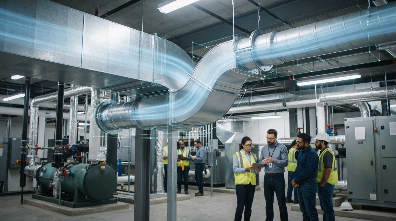
What if the shortest duct transition isn’t the best fit for your system? A transition’s shape and length affect how air moves, while tight clearances and awkward routes can limit the geometry available. Specifying custom HVAC transition fittings is therefore a coordination task, not just a matter of joining two duct sizes.
Airflow and fit both matter. A transition designed without the adjoining ductwork in view can create avoidable coordination problems before fabrication. This article explains how to assess transition geometry, choose a shape for the available space, and provide the dimensions and connection details needed for a clear specification.
We’ll cover the information to define, including inlet and outlet dimensions, orientation, offset, length, and connection details. We’ll also explain how BIM coordination can help resolve routing and fit before production. Velocity Sheet Metal connects coordinated project information to fabricated ductwork through BIM coordination and spiral, round, and rectangular duct capabilities. Careful planning helps the fitting line up with the system it’s built to serve.
Key Takeaways
- Identify a transition by the change it makes between connected duct sections, rather than confusing it with an elbow, tee, or straight run.
- Consider how abrupt area changes and tight geometry may affect airflow and system resistance. A gradual transition is a design consideration, not a performance guarantee.
- Compare rectangular-to-round, round-to-rectangular, and size-reduction configurations against your duct connections and available space.
- Specify custom HVAC transition fittings with dimensions at both ends, fitting length, orientation, and connection details, then review the drawings before release.
- Use BIM coordination to resolve routing and fit details before fabrication, and connect approved design information to the ductwork production process.
What Are Custom HVAC Transition Fittings, and What Do They Connect?
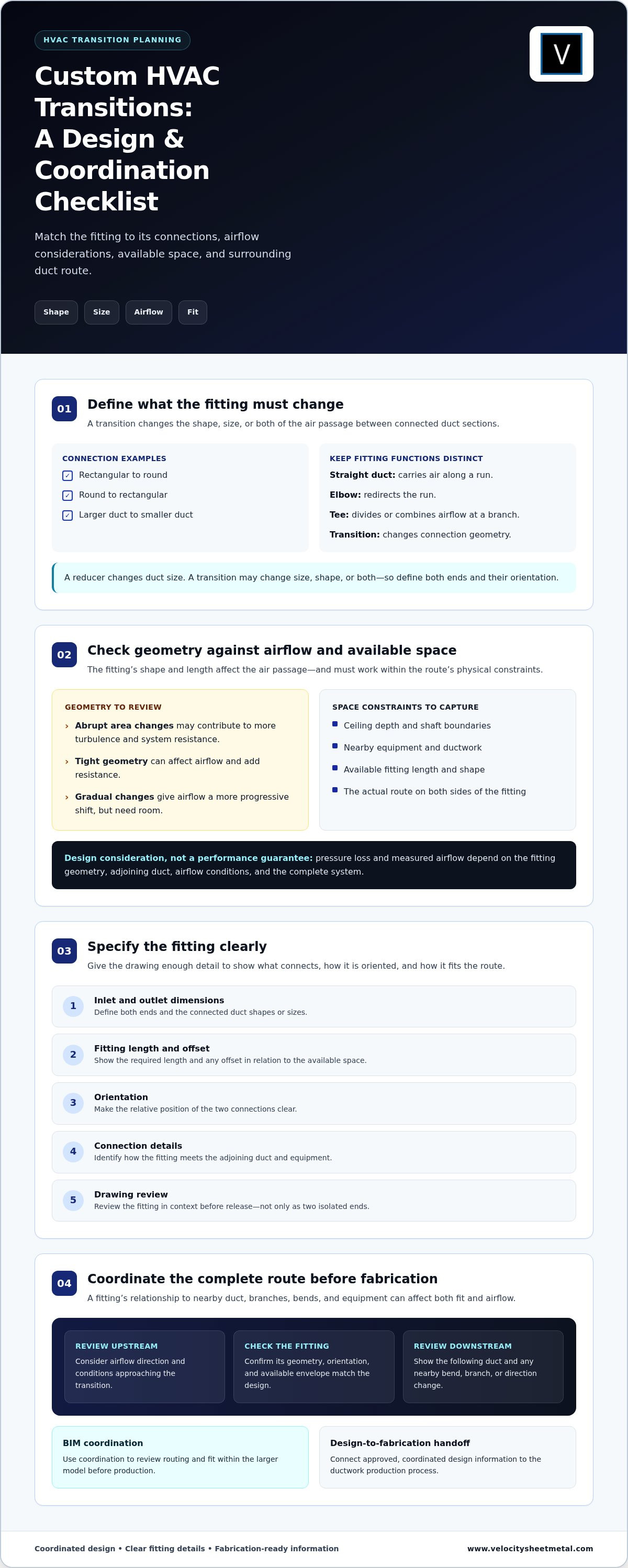
A transition fitting is a duct component that changes the shape, size, or both of the air passage between two connected sections. It bridges differences in adjoining ductwork so the connection can follow the system design and fit the available space. Common examples include rectangular-to-round, round-to-rectangular, and larger-to-smaller duct connections.
Transitions have a different job from other common fittings. A straight duct carries air along a run without changing its cross-section. An elbow redirects the run, while a tee divides or combines airflow at a branch. A transition changes the connection geometry. Some layouts require more than one fitting function, so drawings should show how the transition relates to nearby duct, branches, and equipment.
The choice is part of the wider air-distribution design, not just a matter of matching two openings. Equipment may have a round outlet while the connected trunk is rectangular, or rectangular duct may need to connect to a round run. For context on how ductwork fits into larger HVAC systems and components, consider the complete path from equipment through the distribution network. Geometry at one connection affects how the parts fit together and how air moves through the system.
Custom HVAC transition fittings are useful when standard connection shapes or dimensions don’t match the project. For example, a unit with a rectangular outlet might connect to a round duct route above a ceiling. A rectangular-to-round fitting could bridge those ends, but its orientation and overall envelope must also suit the route. The equipment connection, adjoining duct, clearances, and design requirements determine the appropriate form.
When does an HVAC duct system need a transition?
A transition is needed when equipment and adjoining ductwork have different shapes or dimensions. Ceiling depth, shaft boundaries, and nearby equipment can limit where the connection sits and how much room the fitting has. A round outlet meeting rectangular duct in a restricted ceiling space is one example. The drawing should capture the actual route and constraints rather than assume a standard shape will work.
Transition fitting versus reducer: what is the difference?
A reducer changes duct size, while a transition can change size, shape, or both. A fitting that connects a larger rectangular duct to a smaller round duct combines a size reduction with a shape change. Project drawings and airflow requirements determine the configuration; the labels alone don’t establish its geometry. Define both end connections and their orientation so the fitting’s role is clear.
How Transition Geometry Affects HVAC Airflow and System Resistance
A transition changes the passage air must travel through. If its cross-sectional area changes abruptly, or the fitting forces air through tight geometry, airflow can become more turbulent and system resistance can increase. That added resistance contributes to the pressure loss the system must handle. The effect depends on the change in area and shape, the fitting’s layout, and how it meets the surrounding duct.
Transition performance depends on its geometry and the connected system. A fitting can be designed with airflow in mind, but its shape alone doesn’t determine measured performance. Airflow direction, conditions before the transition, downstream duct, and other system components all influence what happens across the complete route. Treat pressure loss as a system-design consideration, not a number that can be judged from the fitting in isolation.
Why transition length and shape matter
A gradual change gives airflow a more progressive shift in direction or area than an abrupt step, which can support smoother flow. But a longer or more gradual form needs room. Ceiling depth, shafts, equipment, and nearby duct can constrain the available length and shape. There’s no universal angle, ratio, or dimension that suits every project. Geometry must respond to the specified connections, airflow requirements, and actual clearance.
How adjoining ductwork affects transition performance
Review the fitting with the route on both sides. Upstream airflow direction and conditions can affect how air enters the transition, while downstream duct geometry influences what follows. A transition placed near a bend, branch, or another change in direction may behave differently from one with a straight approach and exit. The design drawing should show enough of the route to evaluate these relationships, not just the fitting ends.
Keep design intent separate from measured results. A drawing can define the transition geometry and its connection to adjacent duct, but it can’t by itself prove the installed system’s airflow or pressure performance. Those outcomes depend on the complete system and its operating conditions. For design context, consult ASHRAE standards and guidelines alongside project-specific engineering requirements.
Coordinate the fitting’s shape and available length with the connected duct route before fabrication. BIM coordination can help teams review routing and fit within the larger model. Velocity Sheet Metal connects coordinated project information to physical ductwork through BIM coordination and duct fabrication capabilities. Explore Velocity’s ductwork and fabrication capabilities as you plan the transition handoff.
Which Custom HVAC Transition Shape Fits Your Duct Layout?
Start with the two connections, then fit the transition to the route between them. A rectangular-to-round fitting and a round-to-rectangular fitting may join the same duct shapes, but the direction of the change follows the equipment and adjoining duct. A size reduction may keep one shape throughout or combine a smaller outlet with a shape change. The right configuration depends on the drawings, airflow requirements, and available space.
| Configuration | Connections | Space considerations | Information to define |
|---|---|---|---|
| Rectangular to round | Rectangular end connects to round duct or equipment. | Check available length, orientation, and surrounding clearance for the shape change. | Rectangular width and height, round diameter, fitting length, orientation, and connection details. |
| Round to rectangular | Round end connects to rectangular duct or equipment. | Confirm the route accommodates the transition and that the rectangular end aligns with adjoining duct. | Round diameter, rectangular width and height, fitting length, orientation, and connection details. |
| Size reduction | Larger duct connects to a smaller duct, with shape either maintained or changed. | Review the available run and clearance for the required change in area. | Both end sizes and shapes, fitting length, orientation, and connection details. |
These are layout categories, not standard dimensions. Connection choices and materials should follow the project documents, system requirements, and specified construction approach. The SMACNA duct construction standards provide a reference for duct construction; the project’s design still defines the fitting configuration.
Rectangular-to-round versus round-to-rectangular transitions
Direction matters. If round equipment connects to a rectangular trunk, the fitting must place its round end at the equipment and its rectangular end at the trunk. Reverse the order when the route calls for a rectangular connection leading to round duct. Capture dimensions at both ends and show orientation. A generic product image can’t establish how a fitting aligns in your actual layout.
How to balance limited space with airflow needs
Map available height and width, route direction, nearby obstructions, and access needs before settling on the fitting envelope. A compact square-to-square form may suit a height-restricted route, but reducing height can limit the room for a gradual shape change and involve airflow trade-offs. Coordinate that choice with the project engineer or mechanical drawings rather than assuming compactness and airflow goals automatically align.
Check the proposed geometry against adjacent duct and equipment in plan and elevation views. Confirm the connection orientation, clearances, and dimensions as a set. If the route forces a shorter fitting than the design intent allows, flag the constraint for engineering coordination before the fabrication information is finalized. This keeps the selected shape grounded in the actual system rather than a catalog illustration.
How to Specify a Custom HVAC Transition Fitting
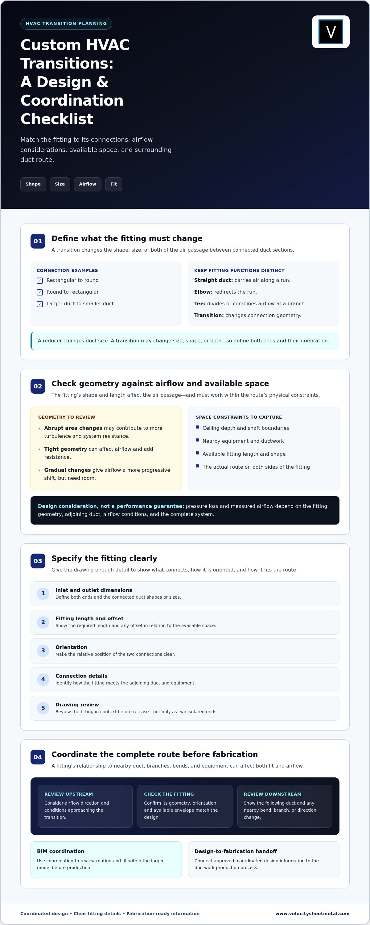
A useful specification does more than name the shapes at each end. It gives the design and fabrication teams enough information to understand the fitting’s position, orientation, interfaces, and relationship to nearby ductwork. Work from the project drawings, and resolve unclear or conflicting dimensions before releasing the fitting for production.
Use this sequence to build a project-ready specification for custom HVAC transition fittings:
- Define both connections. Record the shape and dimensions at the inlet and outlet. Use width and height for rectangular ends, and diameter for round ends.
- Set the fitting length. Show the intended overall length on the drawing, based on the design and available route. Don’t assume a generic image or catalog example represents the required geometry.
- Mark orientation. Identify which end faces the equipment and which connects to adjoining duct. Add plan or elevation views when needed to make offsets and alignment clear.
- Document interfaces. Specify connection style and show flange patterns or other interface details when the project design requires them. Keep choices consistent with the adjoining components and project documents.
- Show the surrounding route. Include nearby ducts, structure, equipment, clearances, and service access. Review the fitting drawings against this context before release.
What dimensions and connection details belong in the specification?
Give each end its own clearly labeled dimensions and shape. For a rectangular-to-round fitting, identify the rectangular width and height and the round diameter, then indicate which end connects to each component. Include fitting length, orientation, and connection details. If the design calls for a flange pattern or another specific interface, show it on the drawing rather than relying on an unstated assumption.
Use the project’s established units and dimensioning conventions throughout. If a dimension is referenced from a face, centerline, or other datum, make that reference clear. A coordinated procurement workflow also depends on complete documentation; the HVAC duct fabrication procurement guide offers related context for organizing fabrication information.
How BIM coordination can catch transition conflicts
Review the fitting in the model alongside nearby ductwork, structure, equipment, and required service access. This can reveal a route or orientation conflict while the geometry is still being coordinated, rather than after fabrication information is released. Resolve clashes with the project team and update the drawings or model so the approved configuration is clear. BIM coordination for sheet metal fabrication explains how coordinated digital information supports the move from design to physical parts.
Before release, compare the final views and dimensions with the connected components. Velocity Sheet Metal provides coordinated duct fabrication and BIM support. Plan your transition fitting with Velocity Sheet Metal.
From Coordinated Design to Custom HVAC Transition Fabrication
A transition moves from design intent to fabrication through a clear handoff. The approved geometry and dimensions must align with the connected duct, equipment, and project layout. Drawings and model information should communicate the fitting’s end connections, orientation, length, and any required interface details. That context lets fabrication information support the transition as part of a coordinated duct system, rather than as an isolated component.
What a coordinated fabrication workflow contributes
Before production, compare the approved fitting geometry with the adjacent duct sections and the route shown in the project documents. BIM coordination helps teams review routing and spatial relationships with nearby structure and equipment, then resolve conflicts before fabrication information is released. Clear drawings reduce ambiguity at the handoff; they don’t guarantee a particular tolerance, schedule, or installation outcome.
At this stage, project teams can make sure the relevant information is aligned:
- Approved end shapes, dimensions, and orientation match the adjoining components.
- Clearances and route constraints are reflected in the coordinated drawings.
- Connection details and any specified interfaces are shown for the fitting.
- Related ductwork is represented clearly in the fabrication information.
With coordinated information in place, Velocity Sheet Metal connects project drawings and BIM coordination to physical ductwork. Its capabilities include automated rectangular duct production, spiral and round duct and fittings, BIM coordination and spool drawings, and on-demand part production. Where a project includes repeatable rectangular duct, coil-line automated rectangular duct can be part of the broader production workflow. Each fitting still needs to follow its approved project geometry and connection details.
Plan the next step for your ductwork project
Prepare the application, dimensions at both ends, fitting orientation, connection details, and layout constraints. Keep the adjacent duct and equipment visible in the drawings or coordinated model. These inputs give the fabrication handoff a defined basis and help the team review the fitting in context before production.
Velocity serves project teams nationwide and ships nationally, connecting coordinated design information to ductwork fabrication. For custom HVAC transition fittings, bring the approved geometry together with the surrounding system details. Explore Velocity Sheet Metal's fabrication capabilities and plan the next step for your ductwork project.
Move Your Transition Design Toward Production
Turn design intent into a decision the project team can carry forward. Treat custom HVAC transition fittings as part of the duct route, not an isolated detail. Keep the approved geometry connected to the surrounding layout as drawings develop, and make unresolved constraints visible before they become fabrication questions. That clarity helps everyone work from the same project information.
A well-prepared fitting specification gives the fabrication process a clear starting point. Velocity Sheet Metal brings BIM coordination together with automated HVAC ductwork and fittings, supported by a management team with more than 50 years of combined industry experience. Its nationwide coverage and shipping support project teams across the United States.
Ready to move from coordinated design to fabricated ductwork? Explore Velocity Sheet Metal's fabrication capabilities and take the next step with confidence.
Frequently Asked Questions
Can a custom transition fitting be used in an existing HVAC system?
Yes. A custom fitting can connect existing ductwork when actual site conditions and system requirements are accounted for. In a retrofit, verify the installed duct dimensions rather than relying only on older drawings, which may not reflect field changes. Also consider nearby access panels, hangers, and equipment clearances. These checks help determine whether custom HVAC transition fittings can work within the existing route without forcing adjoining components out of position.
Is a custom transition fitting the same as an HVAC reducer?
Not necessarily. A reducer describes a change in duct size, while “transition fitting” is a broader term for a fitting that adapts the connection between duct sections. A reducer can be a size-only transition; a fitting may also change the duct shape. For example, a project may need to connect different sizes while changing from round duct to rectangular duct. Use the drawing’s connection details to identify the intended fitting.
What happens if a transition fitting does not fit the ductwork?
Don’t force the connection or alter the fitting in the field without an approved design change. A poor fit can leave gaps, misalign adjoining duct, or interfere with nearby access and supports. Pause the work and compare the fabricated part with the approved drawing and actual connection points. Document the mismatch, including where it occurs, so the project team can determine whether the drawing, field condition, or fitting needs revision.
Does an HVAC transition fitting need insulation?
It depends on the system design and where the fitting is located. A transition may need insulation to match the adjoining duct’s thermal or condensation-control requirements, while other applications may specify a different approach. Check the mechanical drawings and project specifications for the fitting as well as the connected duct. If insulation is required, the design should address continuity at seams and connections instead of treating the fitting as a separate exception.
Can a duct transition be used in an exhaust system?
Yes, a transition can be used in an exhaust route if its configuration and construction suit the system’s design conditions. The conveyed air, operating environment, connection requirements, and project specifications all matter. An exhaust application may have different material or interface requirements than a general supply-air run, so don’t assume the same details apply to both. Follow the mechanical drawings and coordinate the fitting with the surrounding exhaust duct and equipment.
How can I tell whether a transition is contributing to an airflow problem?
Symptoms such as uneven airflow or unusual noise can point to a system issue, but they don’t prove the transition is responsible. Compare measured airflow or pressure with the project’s design information, then inspect the fitting and nearby duct for obstructions, damage, leaks, or misalignment. Also consider other components, such as filters, dampers, and the fan. A system-level assessment helps separate a transition concern from issues elsewhere in the air path.