Sheet Metal Component Manufacturing: The 2026 OEM Engineering Guide
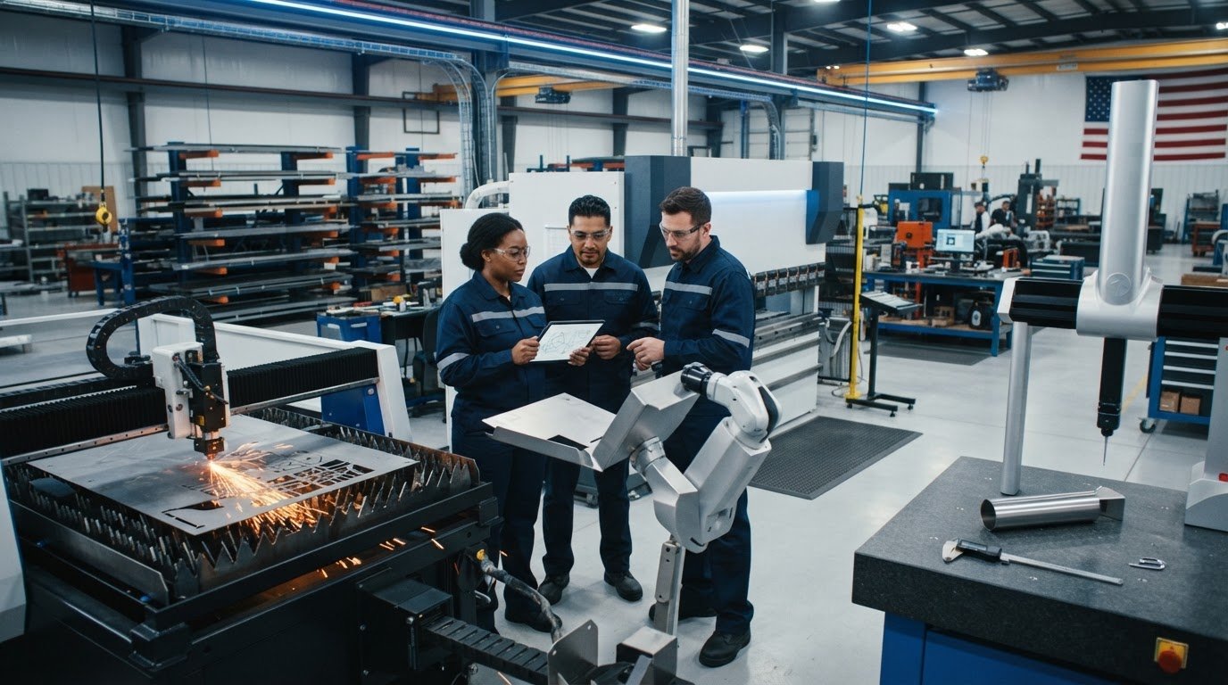
Relying on digital broker platforms for production-scale parts is costing your assembly line far more than you realize. In modern sheet metal component manufacturing, an automated quoting portal can't replace direct shop-floor collaboration when tight CAD geometries hit real-world tooling limits.
You've likely experienced the friction firsthand. Parts arrive with subtle tolerancing discrepancies that trigger fitment failures during final assembly. Minor translation errors between your design files and the press brake spark weeks of supplier delays. Meanwhile, intermediary broker markups quietly inflate your unit costs. You shouldn't have to gamble on batch-to-batch consistency or struggle to get an experienced manufacturing engineer on the phone.
This comprehensive engineering guide gives you the technical processes, design tolerances, and supplier evaluation criteria required to procure high-precision sheet metal components at scale. We'll examine how direct domestic fabrication partnerships, high-speed laser profiling, and closed-loop CNC bending eliminate supply chain bottlenecks while driving down per-part costs.
Key Takeaways
- Master critical DFM fundamentals, including K-factor calculations and hole-to-bend clearances, to prevent flange distortion and assembly fitment failures.
- Upgrade your sheet metal component manufacturing pipeline with high-speed fiber laser cutting and automated CNC press brake bending for pristine edges and tight angular tolerances.
- Eliminate intermediary markups and communication lag by partnering directly with a dedicated domestic fabricator that provides hands-on engineering reviews.
- Execute a structured five-step scaling roadmap backed by First Article Inspection protocols to guarantee part-to-part consistency across high-volume production runs.
What Is Sheet Metal Component Manufacturing in Modern OEM Production?
Sheet metal component manufacturing is the precision engineering discipline of transforming flat metal stock into functional, close-tolerance components through high-velocity cutting, CNC forming, and mechanical fastening. While foundry casting demands expensive tooling molds with inherent porosity risks, and heavy structural fabrication deals with thick plate weldments, precision sheet metal operations focus on thin-to-medium sheet stock. They deliver lightweight, repeatable structural rigidity. Modern industrial lines rely on direct digital fabrication cells to convert flat material into complex three-dimensional geometries without prohibitive tooling lead times.
Precision parts form the physical framework of modern capital equipment. By adhering to standardized sheet metal material specifications and gauges, original equipment manufacturers (OEMs) produce dimensionally stable enclosures, internal mounting frames, and robust brackets. Rather than hogging components out of solid aluminum billets, precision forming leverages cold-working dynamics. It increases mechanical yield strength along the bend axes while slashing raw stock waste and machine cycle hours.
The Role of Sheet Metal in Industrial Machinery and Equipment
Industrial enclosures and internal chassis require high strength-to-weight ratios to protect sensitive electronics and withstand continuous mechanical vibration. Formed sheet components provide structural mounting surfaces without excess bulk. When engineered with formed stiffening ribs, localized gussets, and precise flange returns, thin-gauge sheet matches the rigidity of heavy structural assemblies. This approach also ensures consistent mating surfaces required for strict ingress protection, thermal heat dissipation, and electromagnetic interference shielding.
Digital Engineering Workflows: From 3D CAD to the Shop Floor
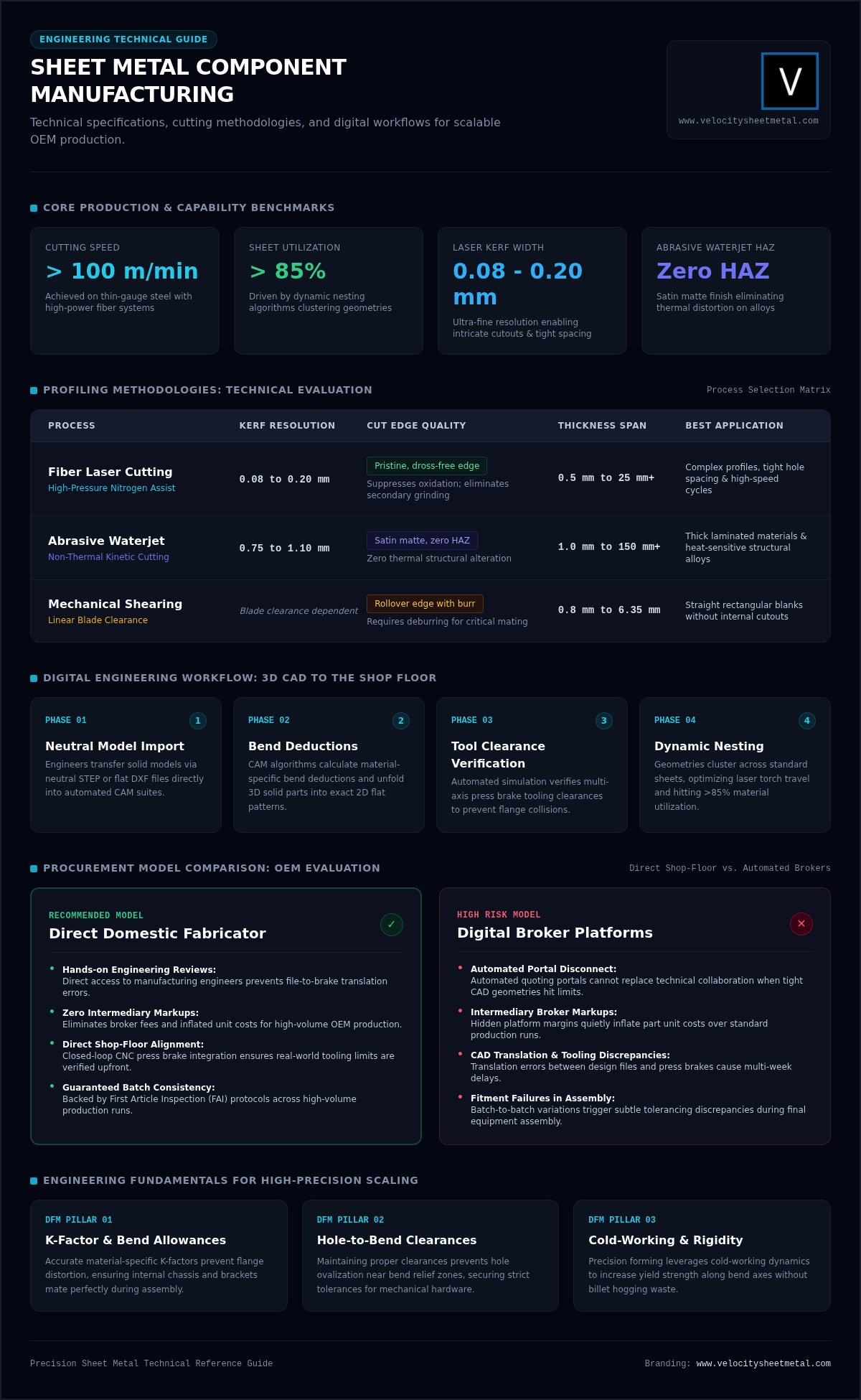
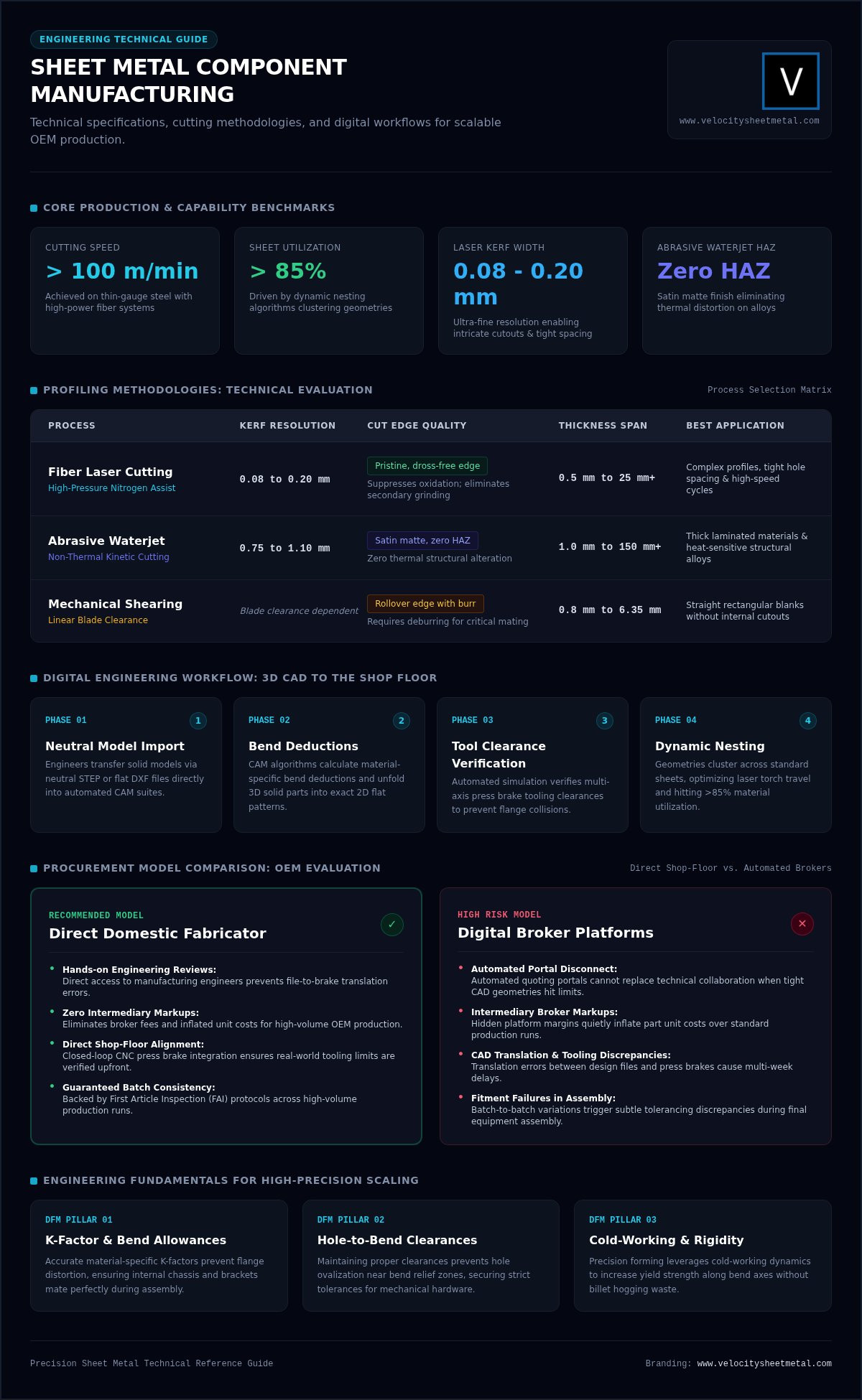
Modern sheet metal component manufacturing runs on synchronized digital pipelines. Design engineers transfer solid models using neutral formats like STEP or flat-profile DXF files directly into automated CAM suites. From there, software algorithms calculate material-specific bend deductions, unfold the 3D geometry into true 2D flat patterns, and verify press brake tooling clearances. Dynamic nesting software then clusters these geometries across standard sheet sizes. This optimizes torch travel paths, reduces cut cycle times, and drives raw material utilization well above 85%.
Core Processes: Cutting, CNC Bending, and Component Assembly
Precision sheet metal component manufacturing relies on three sequential production pillars: thermal or mechanical profiling, multi-axis forming, and structural joining. Choosing the correct method at each phase determines final dimensional repeatability, cut-edge squareness, and overall production costs.
| Process | Kerf Width / Resolution | Cut Edge Quality | Material Thickness Span | Best Fit Application |
|---|---|---|---|---|
| Fiber Laser Cutting | 0.08 mm to 0.20 mm | Pristine, dross-free edge | 0.5 mm to 25 mm+ | Complex profiles, tight hole spacing, rapid cycle times |
| Abrasive Waterjet | 0.75 mm to 1.10 mm | Satin matte, zero HAZ | 1.0 mm to 150 mm+ | Thick laminated materials, heat-sensitive structural alloys |
| Mechanical Shearing | Blade clearance dependent | Rollover edge with burr | 0.8 mm to 6.35 mm | Straight rectangular blanks without internal cutouts |
High-Precision Cutting: Fiber Lasers versus Mechanical Punching
High-power fiber systems dominate modern cutting cells, cutting thin-gauge steel at speeds exceeding 100 meters per minute. High-pressure nitrogen assist suppresses oxidation, eliminating secondary grinding before welding or powder coating. OEMs seeking tight-tolerance profiles routinely specify direct precision laser cutting services for intricate cutout paths. Mechanical CNC turret punches remain efficient for repeating hole grids and formed features like louvers, but lasers provide far superior edge perpendicularity without tooling wear.
Forming Complex Geometries with Multi-Axis CNC Press Brakes
Forming requires precise control over sheet physics. While coining demands massive tonnage and bottoming requires dedicated punch-and-die sets, air bending remains the industry standard for production versatility. Multi-axis CNC backgauges position blanks within fractions of a millimeter across sequential bends. To prevent angular variation along parts, machines utilize dynamic crowning compensation systems to offset ram deflection under load. Implementing sound design for manufacturing principles helps eliminate cracking along the outer bend radius. OEM buyers can review operational parameters in our guide to CNC press brake services for OEMs, or study flange deformation root causes in our breakdown of common press brake forming defects.
Fastening and Assembly: Hardware Insertion and Welded Seams
Once blanks are formed, secondary operations complete the structural subassembly. Hydraulic insertion presses seat self-clinching PEM nuts, threaded studs, and standoffs flush into laser-cut pilot holes, providing load-bearing threads in thin material. Welded seams combine structural rigidity with environmental sealing. High-precision TIG welding handles visible, cosmetic exterior corners, while MIG welding handles heavy-gauge internal structural joints. For overlapping sheet flanges, automated resistance spot welding delivers secure joints with zero filler material.
If your project demands tight-tolerance forming alongside laser cut accuracy, you can partner directly with our domestic fabrication team to streamline your component line.
Design for Manufacturability (DFM): Tolerances, Bend Radii, and Materials
Designing for manufacturability bridges the gap between CAD theory and metal deformation. Unlike CNC milling, where cutting tools hold sub-thousandth tolerances across solid blocks, sheet metal component manufacturing works with material stretch, grain orientation, and springback. Achieving repeatable fits requires following core geometric rules:
- Standardize Inside Radii: Use a single inside bend radius across the entire part to eliminate secondary tool changes.
- Maintain Flange Heights: Keep flange lengths at least 4x to 6x sheet thickness ($t$) so the part spans the lower V-die opening securely.
- Isolate Openings: Position cutouts and extruded holes at least $2.5\times t + R$ away from bend tangents to prevent ovalization.
- Add Corner Reliefs: Extend rectangular or teardrop relief notches at least $1\times t$ past bend lines to stop edge tearing.
Calculating Bend Allowances, Deductions, and K-Factors
When metal bends, the inside surface compresses while the outer surface stretches. The neutral axis, where no dimensional change occurs, shifts inward. The K-factor expresses this ratio of neutral axis depth to total material thickness, typically settling between 0.30 and 0.45 for air bending. Never rely on default CAD assumptions. Your flat blank calculations must match the shop floor tooling, punch radius, and die width used on the press brake. Bending perpendicular to the rolling grain avoids outer fiber fractures, whereas bending parallel to the grain invites structural cracking along the bend line.
Critical Geometry Rules: Hole Reliefs, Flange Lengths, and Cutouts
Cutouts placed too close to a bend radius draw into the forming zone, warping the hole geometry and throwing hole-to-hole centerlines out of spec. If a hole cannot sit $3\times t$ away from the bend line, cut a relief slot between the feature and the bend tangent. Flange heights shorter than the die shoulder drop into the tooling opening, causing severe angular variation. Fabricators operating automated forming equipment adhere to strict OSHA mechanical power press regulations to run continuous, high-speed setups while maintaining dimensional repeatability.
Selecting the Right Alloy and Gauge for Industrial Performance
Material temper dictates forming limits. Aluminum 5052-H32 bends easily at a tight $1\times t$ inside radius, making it ideal for electronic enclosures. In contrast, precipitation-hardened 6061-T6 demands a generous $2\times t$ to $3\times t$ radius to prevent outer fiber rupture. For general chassis, cold-rolled mild steel offers predictable forming at low cost, while pre-galvanized G90 sheet provides bare edge protection without post-plating. When specifying 304 or 316 stainless steel, account for rapid work-hardening; stainless requires roughly 50% more tonnage than mild steel and exhibits significant angular springback.
Direct Fabricator vs. Broker Platform: Evaluating Manufacturing Partners
Procuring production-grade parts requires choosing between two fundamentally different business models: broker networks and direct manufacturing facilities. Digital broker platforms aggregate machine capacity through automated web portals. They excel at rapid, low-volume prototyping where instant pricing matters more than unit cost. When scaling precision sheet metal component manufacturing to production volumes of 500 units or more, that broker layer introduces distinct friction points.
| Evaluation Factor | Digital Broker Platform | Direct Contract Fabricator |
|---|---|---|
| Pricing Transparency | Includes intermediary gross margin markup (often 15% to 35%) | True direct machine-hour and material costs |
| Design Feedback | Automated, algorithmic DFM geometry checks | Direct review with experienced machine operators |
| Batch Consistency | Split orders across multiple uncoordinated third-party shops | Single-facility production using dedicated press tooling |
| Traceability | Obscured supply tiers with mixed mill lots | Direct Mill Test Reports (MTRs) and verifiable melt batches |
The Broker Dilemma: Margin Stacking and Disconnected Engineering
Brokers sit between your design team and the machines cutting your metal. That middleman layer creates communication drag. When a complex multi-flange bend creates tooling interference, an automated portal cannot suggest an alternative relief notch. Instead, technical revisions filter through non-technical customer service reps, wasting days. Even worse, reorders often route to entirely different sub-tier shops. Different machinery, varied tooling conditions, and mixed sheet stock then lead to assembly-line fitment failures.
Benefits of Direct Engineering Collaboration with the Shop Floor
Partnering directly with a dedicated manufacturer puts your CAD team in immediate contact with skilled operators. If a critical hole sits close to a bend tangent, an operator can immediately recommend adjusting the internal radius or dropping into a narrower V-die. This level of collaboration eliminates administrative delays. You secure single-source accountability, exact material lot traceability, and tooling setups calibrated specifically for your run.
Auditing Vendor Capabilities, Quality Systems, and Track Records
Always audit a fabricator's quality infrastructure before issuing high-volume purchase orders. Confirm they operate high-power fiber lasers, modern CNC press brakes with dynamic crowning, and calibrated measurement equipment like FaroArms or optical comparators. Ensure their quality management system meets current ISO standards and supports structured First Article Inspection (FAI) reporting. Bypassing intermediary networks protects your component tolerances, supply chain schedules, and unit margins.
Ready to cut broker markups out of your supply chain? Connect directly with our engineering team to review your CAD models and request a production quote.
Scaling Production: From First-Article Prototype to High-Volume Runs
Ramping up sheet metal component manufacturing from a single engineering sample to thousands of production units requires a disciplined, repeatable framework. Moving directly into mass production without intermediate checkpoints invites catastrophic scrap rates and tooling wrecks. Industrial OEMs follow a proven five-step roadmap:
- DFM & Tooling Review: Interrogate CAD geometry against shop-floor tooling libraries, press brake tonnages, and laser kerf offsets.
- First-Article Fabrication: Cut and form short-run physical prototypes to prove flat pattern calculations and bend deductions.
- FAI Verification: Execute dimensional measurement against 2D blueprint callouts using calibrated metrology arms and height gauges.
- Production Nesting & Batch Cutting: Group parts dynamically across master sheet stock to maximize raw material yield and cycle efficiency.
- Finishing, Packaging & Logistics: Apply secondary protective surface treatments, package for abrasion resistance, and stage shipments.
First-Article Validation and Tolerance Verification
First Article Inspection (FAI) serves as the gatekeeper for volume runs. Quality inspectors verify every ballooned dimension on the 2D engineering drawing using calibrated CMMs, optical comparators, and surface roughness gauges. Beyond raw measurements, physical fit checks with mating subassemblies prevent cumulative tolerance stack-ups from stalling factory assembly lines. Formal FAI documentation must be signed off before raw sheet inventory is released to automated cutting cells.
Batch Optimization and Surface Finishing Operations
High-volume efficiency depends on dynamic nesting software that clusters multiple production part numbers across standard sheet sizes. This strategy balances machine runtimes, clears laser paths cleanly, and drops skeleton scrap rates. After profiling, mechanical deburring brushes and edge-rounding tumblers remove microscopic dross and break sharp edges to ensure technician safety. For parts needing corrosion protection, subassemblies route to chemical conversion, zinc plating, e-coating, or automated architectural powder-coating lines to meet strict salt-spray exposure standards.
Packaging, Palletizing, and Nationwide Freight Distribution
Precision fabrication means nothing if parts arrive twisted or scratched. Heavy-duty crating utilizes timber pallets, closed-cell foam interleaving, and structural perimeter banding to prevent movement during transit. Unfinished cold-rolled and carbon steels receive Vapor Corrosion Inhibitor (VCI) wrapping to block ambient humidity and moisture during transport. To support lean manufacturing workflows, OEMs establish scheduled blanket orders and staged releases. This practice guarantees a reliable flow of identical parts straight to your assembly bays without consuming your warehouse footprint.
Ready to move your components into high-volume production? Submit your CAD files to Velocity Sheet Metal to review your design with our fabrication engineers.
Take Control of Your Precision Component Supply Chain
Reliable production comes down to disciplined DFM practices, verified bend allowances, and eliminating the administrative friction of broker portals. Scaling tight-tolerance parts doesn't require compromising on quality or paying inflated intermediary fees. When you streamline CAD-to-machine handoffs, precision sheet metal component manufacturing becomes a competitive advantage for your assembly line.
Bringing your components from digital design to volume production requires an experienced domestic partner. At Velocity Sheet Metal, we house modern high-speed fiber laser cutting and precision CNC press brake forming under one roof. You work directly with seasoned manufacturing engineers who understand cold-forming physics, cutting out broker delays and split-batch inconsistencies. Backed by a dependable nationwide shipping infrastructure, we deliver production-ready components straight to your facility floor.
Eliminate fitment errors and lead time bottlenecks on your next production run. Request an Engineering Review & Fabrication Quote to get started today.
Frequently Asked Questions
What is the standard tolerance range for precision sheet metal component manufacturing?
Standard industrial tolerance for laser-cut profiles sits at ±0.005 inches (±0.13 mm), while press brake forming typically holds ±0.015 inches (±0.38 mm) on linear flange dimensions and ±1.0 degree on angular bends. Tighter tolerances are achievable depending on material thickness, alloy temper, and part geometry. However, stacking tolerances across multiple bends requires explicit geometric dimensioning and tolerancing (GD&T) callouts to ensure repeatable assembly.
How does sheet metal thickness gauge translate to inches and millimeters?
Gauge numbers represent standard sheet thickness ranges, but exact decimal dimensions vary by material classification. For example, 16-gauge carbon steel measures roughly 0.0598 inches (1.52 mm), while 16-gauge aluminum measures 0.0508 inches (1.29 mm) because ferrous and non-ferrous alloys use different historical gauge systems. Engineering blueprints should always call out nominal thickness in decimal inches or millimeters rather than gauge numbers to eliminate procurement ambiguity.
Can tight bend radii cause cracking in aluminum and stainless steel parts?
Forcing an inside bend radius below material thresholds causes severe tensile stress and outer fiber fractures. Heat-treated alloys like 6061-T6 aluminum crack easily unless formed with an inside radius of at least 2x to 3x material thickness. Austenitic stainless steels like 304 work-harden quickly during deformation. They require punch radii matched to their tensile properties to prevent micro-fracturing along the outside of the formed bend.
What is the difference between air bending and bottom bending on a CNC press brake?
Air bending forms angles by pressing the sheet into a V-die without contacting the bottom, controlling angle depth via punch stroke position. This method uses less tonnage and handles multiple angles with a single tooling set. Bottom bending forces the sheet fully against the die faces, requiring higher tonnage and dedicated punch-and-die sets for each specific angle. Air bending remains the primary choice for flexible production.
Why do direct fabrication shops often outperform automated broker platforms?
Direct fabricators give OEMs direct access to the manufacturing engineers and machine operators cutting their parts. Automated broker platforms add a 15% to 35% margin markup and route orders across unvetted third-party networks, causing communication lag and batch variations. A dedicated domestic partner provides single-source quality control, shared tooling records, and verified material certs, ensuring repeatable sheet metal component manufacturing across volume production runs.
What surface finishing options are available for sheet metal components?
OEM components support mechanical deburring, edge rounding, and a range of protective finishes. Common treatments include architectural powder coating for impact resistance, clear or color anodizing for aluminum, and zinc electroplating or passivation for carbon and stainless steels. Selecting the right finish depends on your operational environment, such as salt-spray corrosion resistance, electrical conductivity, or cosmetic exterior requirements.
How does grain direction affect the strength and formability of sheet metal?
Sheet metal develops a directional grain structure during mill rolling. Bending transverse (perpendicular) to the grain provides the highest resistance to cracking, allowing tighter radii. Bending parallel to the grain stresses the material along its natural tear lines, increasing the likelihood of edge fracturing. CAM programmers orient parts across nested sheets so high-stress flanges bend across the grain whenever structural loads are severe.
How do you package and protect finished sheet metal parts during nationwide shipping?
Transport protection requires custom wood pallets, corner edge guards, and high-density foam interleaving between stacked components to eliminate vibration scratching. Unfinished steel parts receive Vapor Corrosion Inhibitor (VCI) wrapping or sealed poly bags to block atmospheric moisture during transit. Heavy steel strapping secures the entire stack to the pallet base, preventing lateral shifting when freight moves across nationwide line-haul logistics networks.