Rooftop Unit Curb Adapters: Sizing and Selection Guide
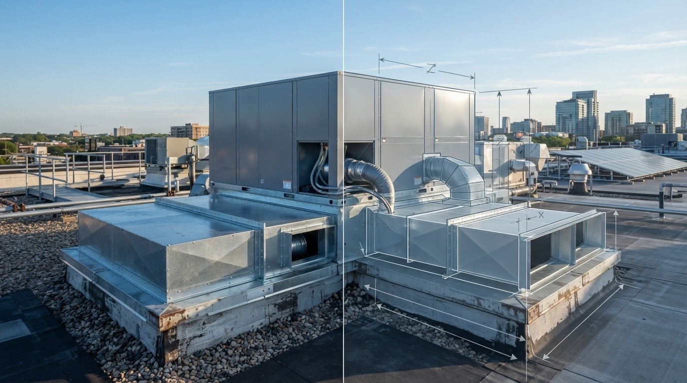
A replacement rooftop unit can fit the roof and still miss the curb. That mismatch is why rooftop unit curb adapters should be selected from verified dimensions, not a catalog guess.
The key measurements are the existing curb footprint, the replacement unit’s base and rail dimensions, and the locations of its supply and return openings. The available height and nearby obstructions matter too. Incomplete field notes or equipment documents can leave these details unresolved until fabrication or roof work is underway.
This guide explains what to gather before requesting an adapter, how to compare curb and unit dimensions, and what to consider when choosing between adapting an existing curb and evaluating its replacement. It also covers the role of coordinated drawings in translating design intent into fabrication information. Start by documenting both sides of the connection, then resolve discrepancies before releasing the work for production.
Key Takeaways
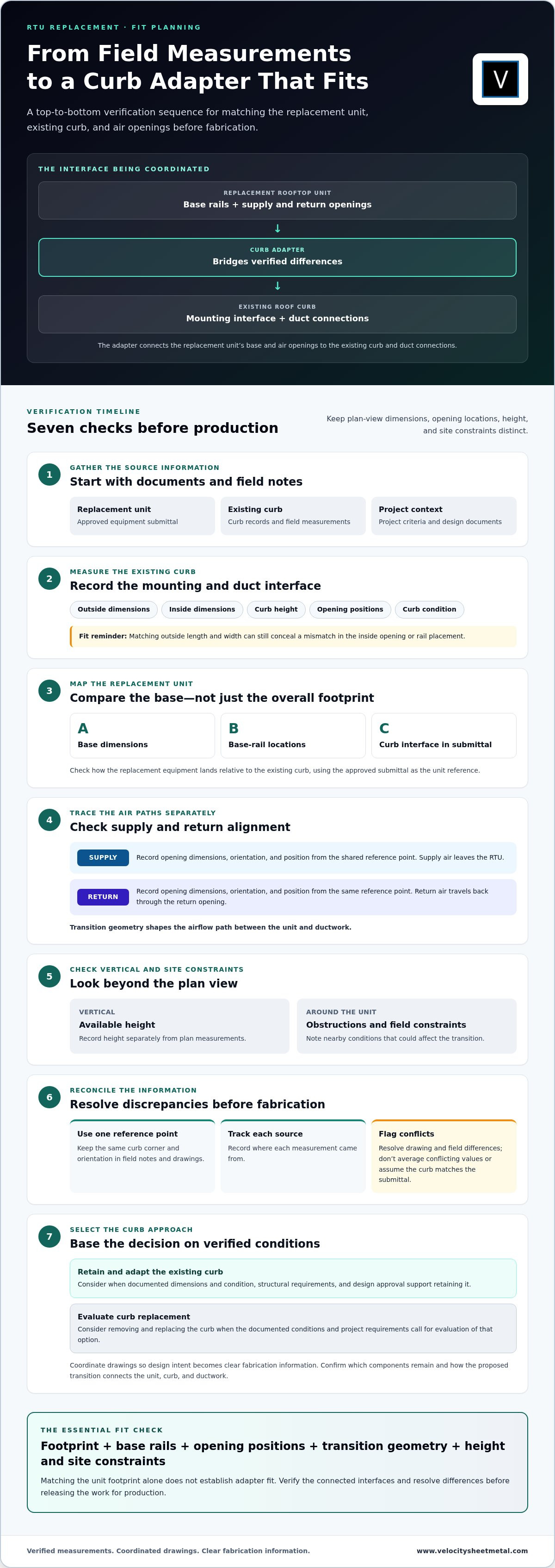
- Compare the existing curb footprint with the replacement RTU base and opening locations before selecting an adapter.
- Track supply and return orientation separately because transition geometry shapes the airflow path between the unit and ductwork.
- Decide whether to retain or replace the curb based on documented dimensions, condition, structural requirements, and design approval.
- Use a sizing checklist to organize manufacturer submittals, curb records, field measurements, and project criteria.
- Verified measurements and coordinated drawings give rooftop unit curb adapters a clearer basis for fabrication.
What Rooftop Unit Curb Adapters Solve in an RTU Replacement
A replacement rooftop unit may serve the same building and connect to the same ductwork, yet have a different base footprint or different supply and return opening locations. The existing roof curb was built around the original equipment. If the new unit’s interfaces don’t align, the project needs a planned transition between the unit and the curb.
A curb adapter is a fabricated interface that bridges those differences. It connects the replacement RTU’s base and air openings to the existing curb and duct connections. The existing roof curb supports the rooftop unit at the roof opening; a curb adapter bridges the mismatch between that curb and the replacement unit.
How the existing curb connects the RTU to the building
The curb sits at the roof opening and provides a mounting interface for the rooftop unit. It also frames the path between the unit and the building’s ductwork: supply air leaves the RTU through the supply opening, while return air travels back through the return opening. The curb, roof opening, and surrounding roof assembly form a connected interface, so their dimensions and project requirements need to be considered together.
That relationship matters beyond the unit’s footprint. The curb must meet the project’s structural and roof-interface requirements, while the air paths need to connect to the intended ductwork. An adapter bridges the equipment-to-curb interface. It doesn’t replace review of the roof assembly or the approved project design.
Why a replacement RTU may need an adapter
Replacement equipment can have a different base size, opening dimensions, or supply and return arrangement than the unit it replaces. Even a unit selected for the same general application may not land directly over the existing curb openings. The mismatch is both geometric and functional: the unit must connect at the curb, and its air openings must align with the duct paths below.
One option is to adapt the connection while retaining the existing curb. Another is to evaluate removing and replacing the curb. The right approach depends on documented curb dimensions and condition, structural requirements, and design approval. An adapter may make it possible to retain a compatible curb, but it doesn’t automatically resolve every roof modification or field condition.
Before fabrication, compare the existing curb and duct interfaces with the replacement unit’s approved submittal. Confirm which components will remain, where the supply and return openings sit, and how the proposed transition will connect them. If records are incomplete or field conditions differ from drawings, resolve those details against approved project documents before releasing the adapter for production.
Early coordination gives the fabricator a defined interface to work from and helps the project team identify fit questions before they become field adjustments. Rooftop unit curb adapters are most effective when their purpose is clear: bridge verified differences between the replacement RTU and the existing curb while accounting for the roof and duct connections around them.
Which Dimensions and Airflow Interfaces Determine Curb Adapter Fit?
Adapter fit depends on more than whether the replacement RTU’s base appears to cover the existing curb. The curb footprint, unit base rails, opening locations, vertical height, and available clearances each describe a different part of the interface. Compare them as separate inputs, using approved submittals and field-verified information rather than relying on a single overall dimension.
Matching the unit footprint alone doesn’t establish adapter fit. The curb interface, opening positions, transition geometry, and vertical constraints must also work together.
Compare the existing curb and replacement RTU geometry
Keep plan-view measurements distinct from height and site constraints. Record the curb’s outside and inside dimensions, curb height, and opening positions. Then compare those details with the replacement unit’s base-rail dimensions and the curb interface shown in its submittal. Matching outside length and width can still conceal a mismatch in the inside opening or rail placement.
| Interface to compare | Information to record | Why it matters |
|---|---|---|
| Existing curb footprint | Outside and inside dimensions, curb height, and opening positions | Defines the existing mounting and duct interface. |
| Replacement RTU base | Base dimensions, rail locations, and interface shown in the approved submittal | Shows how the new equipment lands relative to the curb. |
| Supply and return openings | Opening dimensions, orientation, and position from a shared reference point | Shows whether the air paths connect as intended. |
Use one reference point and a consistent orientation for all plan measurements. For example, identify the same curb corner in field notes and drawings. This makes offsets easier to compare and reduces uncertainty about which side a dimension describes. Record vertical height separately, along with overhead or nearby obstructions and other field constraints that could affect the transition.
If a drawing conflicts with field measurements, or a dimension lacks a clear reference, flag it for resolution before fabrication. Don’t average conflicting values or assume the equipment submittal reflects the as-built curb. Record the source of each measurement so the project team can review the discrepancy.
Check supply and return alignment
For each opening, document its width and length, orientation, and position from the shared reference point. Identify supply and return separately. This reveals whether an opening is centered, offset, or oriented differently from the duct path it must meet.
A transition connects openings that don’t align directly. Its geometry determines how the air path moves from the RTU to the existing duct interface. The project’s airflow and pressure-drop requirements should guide design review; don’t assume a particular transition shape will meet them without evaluation. Keep supply and return paths distinct in drawings and coordinate their locations with the approved project documents.
Clear interface drawings turn these comparisons into a usable fabrication basis. Velocity Sheet Metal’s curb adapter fabrication and BIM coordination connect dimensional information with a coordinated sheet metal workflow. Rooftop unit curb adapters can then be developed around documented interfaces, with unresolved dimensions identified before production.
Curb Adapter Options Compared: Adapt the Existing Curb or Replace It?
The choice isn’t simply “adapter or no adapter.” First establish whether the existing curb can remain part of a compatible, approved assembly. Retaining it may be practical when its condition and interfaces are documented and the replacement RTU can connect through a designed transition. If the curb is damaged, incompatible, or poorly documented, evaluate whether replacement is necessary.
Reuse is a project decision, not an assumption. It depends on verified dimensions, curb condition, structural requirements, coordinated supply and return paths, and design approval. Rooftop unit curb adapters can bridge differences between equipment and an existing curb, but they don’t determine whether that curb is suitable for continued use.
When adapting an existing curb may suit the project
Keeping the curb in place may be worth evaluating when its geometry is compatible with the proposed interface, its condition is acceptable, and the supply and return paths can be coordinated. A fabricated adapter can provide a transition between the replacement unit and the retained curb. Roof assembly and structural conditions still require project-specific review; they can’t be inferred from dimensions alone.
Use the project documents to distinguish a workable reuse case from an unresolved one. A clear curb record, consistent field information, and an approved equipment interface give the team a basis for assessment. Where the opening positions differ, the proposed transition still needs to meet the design’s airflow intent and applicable project criteria.
Configurations can vary in how they reconcile the equipment base with the curb and duct openings. For example, a transition may connect offset interfaces or preserve a more direct path where openings align. These describe different geometries, not a universal menu of solutions. The appropriate configuration must follow the project’s requirements and approved design.
When the project team should evaluate curb replacement
Further evaluation is warranted if the existing curb is visibly damaged, its dimensions conflict across records, or its interfaces can’t be reconciled with the replacement unit. Missing documentation matters too: without reliable information, the team may not be able to establish compatibility for fabrication or approval. Don’t treat uncertainty as proof that the curb is reusable.
Replacement evaluation involves more than equipment fit. Structural capacity, roofing conditions, code requirements, and the new unit’s interface all need review by the qualified project team. The project engineer’s applicable design requirements should guide the decision. Neither retaining the curb nor replacing it should be assumed to satisfy those requirements before review.
- Retain and adapt: Consider when the curb’s documented condition and geometry support a designed connection.
- Evaluate replacement: Consider when damage, incompatibility, structural questions, or missing records leave reuse unresolved.
Once the approach is approved, complete drawings help translate the decision into a clear fabrication basis. Velocity Sheet Metal fabricates custom curb adapters as part of a coordinated sheet metal workflow, with BIM coordination available to support design-to-fabrication handoffs. Final dimensions and project criteria should align with approved documents before production begins.
A Rooftop Unit Curb Adapter Sizing Checklist for Project Teams
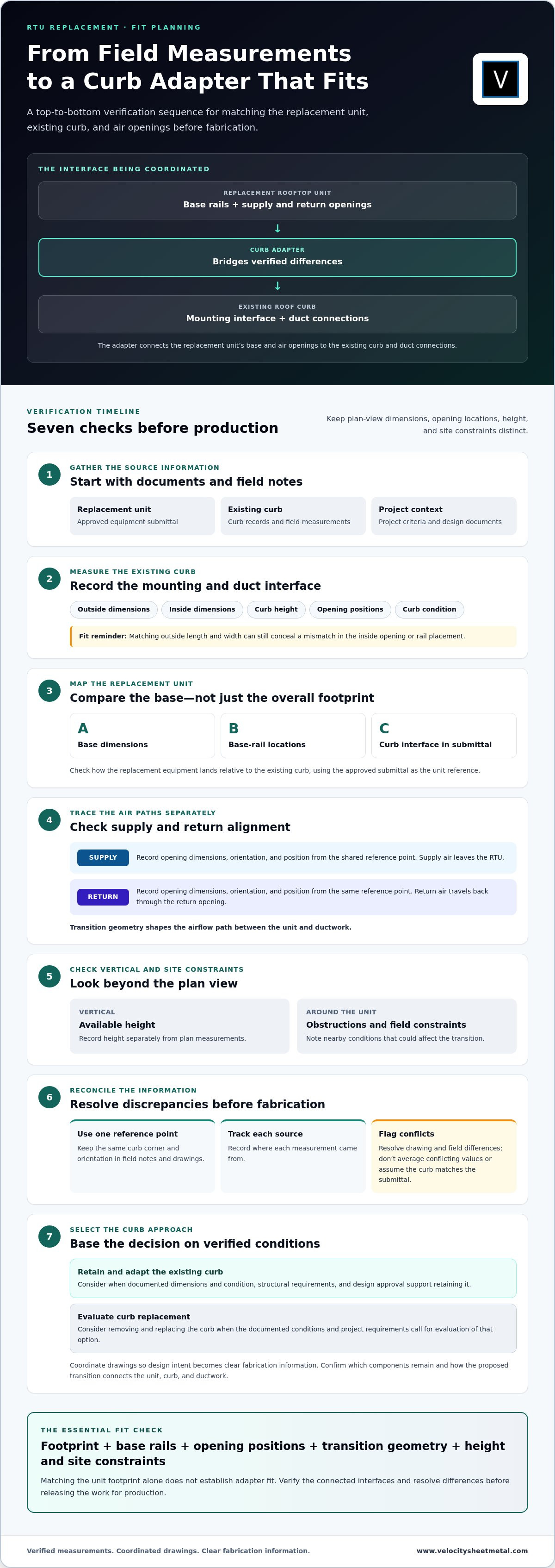
A complete information package gives the project team and fabricator a common basis for review. Keep manufacturer data, existing-curb records, field measurements, and design criteria distinct. This makes missing inputs visible and helps prevent assumptions from carrying through to fabrication drawings.
Collect existing-curb and replacement-unit information
Start with the equipment and the curb as separate records. Use approved submittals for the replacement unit, then compare them with curb documentation and site measurements. Label each drawing and photo with its orientation, reference point, and whether it shows supply or return. An unlabeled opening can be easy to misread during coordination.
- Identify the replacement RTU. Record the manufacturer, model, and approved submittal revision. Capture base dimensions, base-rail locations, and supply and return opening dimensions, positions, and orientation.
- Gather existing-curb records. Note available drawings, schedules, and prior equipment information. Record curb dimensions, height, condition, and identifiable reference points shown in those records.
- Verify field conditions. Measure the curb and openings from a consistent corner or datum. Keep plan dimensions separate from height. Photograph the curb, openings, nearby obstructions, and access constraints, adding labels and orientation notes to each image.
- Assemble project design criteria. Collect approved requirements for materials, insulation, gasketing, clearances, airflow, and structural review where specified. Treat these as project inputs, not assumptions about a standard adapter.
- Review and reconcile drawings. Compare field measurements with the available drawings and submittals. Mark discrepancies, identify which information needs resolution, and have the responsible project team review final dimensions and interface assumptions before fabrication.
Resolve design and field information before fabrication
Don’t silently choose between a drawing and a field measurement when they disagree. Record both, identify the location and dimension in question, and route it for project review. Apply the same discipline to unclear units, missing datums, or a photo that doesn’t show which side of the unit is being viewed. Resolve ambiguity before it becomes a shop-drawing interpretation.
Use the checklist below as a quick completeness check, and attach supporting documents rather than relying on a summary alone. Rooftop unit curb adapters depend on coordinated interface information. Final dimensions and requirements should match approved project documents.
| Input group | Ready to submit when you have |
|---|---|
| Manufacturer submittals | RTU identification, base interface, opening dimensions, and orientation |
| Existing-curb records | Available drawings, dimensions, height, condition, and reference points |
| Field verification | Consistent measurements, labelled photos, and noted site constraints |
| Design criteria | Applicable material, insulation, gasket, clearance, airflow, and structural requirements |
| Drawing review | Discrepancies resolved and final interfaces reviewed by the responsible project team |
With the information assembled, submit your curb adapter project information for coordinated fabrication review.
From Verified Measurements to Custom Curb Adapter Fabrication
Verified measurements turn a sizing checklist into a fabrication basis. Approved equipment submittals, curb dimensions, opening locations, and project criteria give design and fabrication teams a shared set of inputs. Marked-up drawings show the intended interfaces, while clearly identified field discrepancies make it easier to see what needs resolution before work moves forward.
Velocity Sheet Metal fabricates curb adapters as part of a coordinated sheet metal workflow. BIM coordination can help teams review geometry and trade interfaces before fabrication, supporting a clearer handoff from design information to a physical component. For background on that process, explore BIM coordination for sheet metal fabrication.
Coordinate drawings, fabrication details, and project requirements
Start with the latest approved drawings and submittals. Mark the existing curb interface, replacement-unit base, supply and return openings, and relevant clearances. Use consistent orientation notes across drawings, photos, and measurements so each interface can be interpreted the same way. Where project-specific requirements apply to materials, insulation, gasketing, or structural review, show them in the documents used for coordination.
Clear inputs help flag unresolved geometry before fabrication begins. BIM coordination and spool drawings can support review of how the adapter relates to connected sheet metal and other documented interfaces. Resolve conflicts through the project team, then carry approved dimensions and assumptions into the final production information.
Prepare a clear curb adapter project request
A concise request doesn’t need to be complicated. Assemble the records that show both sides of the connection, then identify the approved source for each critical dimension. If a field measurement differs from a drawing, include both and mark the discrepancy rather than choosing one without review.
- Replacement RTU manufacturer, model, and approved submittals
- Existing-curb drawings, dimensions, height, and condition notes
- Supply and return opening sizes, positions, and orientation
- Labelled field photos showing reference points and site constraints
- Applicable project criteria and reviewed interface drawings
That package gives a fabricator a clearer basis for developing a project-specific component. Rooftop unit curb adapters are custom sheet metal work, so dimensions and requirements should be carried forward from approved project information rather than assumed from a typical layout.
Velocity Sheet Metal fabricates the adapter and offers nationwide shipping. The project team should coordinate installation and applicable site work using the approved project documents.
Have the equipment and curb information ready? Discuss your curb adapter project with Velocity Sheet Metal and move from verified project data to a coordinated fabrication handoff.
Move Your RTU Replacement Toward Fabrication
Make the next step a coordinated handoff, not another round of guesswork. Gather the approved drawings, field notes, and project criteria, then bring unresolved interface questions into the fabrication discussion. This gives the team a practical starting point for turning rooftop unit curb adapters from a sizing challenge into a defined project component.
Velocity Sheet Metal fabricates curb adapters with BIM coordination and spool drawing capabilities to support design-to-fabrication communication. Its management team brings more than 50 years of combined industry experience, and the company offers nationwide shipping. Clear project information helps connect the design intent to the fabricated component and supports coordination with the project’s installation team.
Ready to move from verified project information to a fabrication discussion? Discuss your curb adapter project with Velocity Sheet Metal. Bring the details you have, identify anything still being resolved, and take the next step toward a coordinated fabrication handoff.
Frequently Asked Questions
Can a curb adapter fit any replacement rooftop unit?
No. A curb adapter must be designed around the specific replacement unit and the existing roof interface. Two units with similar base dimensions may still differ in rail placement or supply and return opening arrangements. For example, an opening shifted toward one side can require a different transition layout than a centered opening. Use the correct approved submittal revision and confirm project-specific interfaces before treating a unit as a fit.
Does a rooftop unit curb adapter change the height of the new unit?
It can affect the installed elevation, depending on the adapter design and the existing curb arrangement. That change may matter if the unit has nearby obstructions, connected ductwork, or other elevation constraints. Don’t rely on a nominal adapter height to establish the final position. Have the project team review the complete assembly height and required clearances against the approved drawings and site conditions before fabrication.
Can an existing roof curb be reused if it shows corrosion or damage?
Visible corrosion or damage calls for evaluation before reuse, not an automatic decision either way. The project team needs to determine whether the affected areas compromise the curb’s condition or intended interface. For example, deterioration near a connection point may raise different concerns than surface discoloration. Document what’s visible and have the responsible design professional assess the curb against project structural and roofing requirements.
Do curb adapters affect rooftop unit airflow or static pressure?
They can. A transition’s dimensions and geometry influence how air moves between the RTU openings and connected ductwork, so the adapter should be included in the system’s design review. Static pressure and airflow requirements should come from the project design, not assumptions about a typical adapter. If the proposed layout changes the air path, the responsible mechanical design team should evaluate it against the system criteria.
What should project teams do when field measurements conflict with RTU submittals?
Pause the affected interface decision and document the discrepancy. Record the field measurement, its reference point, and the relevant submittal dimension, then identify the exact curb or opening involved. Don’t average the values or quietly substitute one source for the other. Route the conflict to the responsible project team for resolution, and use the reviewed dimension in the final drawing package.
Are curb adapters appropriate for every roof type?
No single adapter approach should be assumed to suit every roof assembly. The roof opening, existing curb arrangement, roofing details, and project requirements all affect whether an adapter is appropriate and how the interface should be addressed. For example, a roof alteration may involve requirements beyond equipment alignment. The project’s qualified design team should review roof and structural conditions before approving the adapter design for fabrication.
What information should be included with a curb adapter drawing package?
Include the replacement RTU identification and approved submittals, existing curb dimensions and condition notes, and supply and return opening locations with clear orientation references. Add field measurements, labelled photos, applicable project criteria, and marked-up drawings showing unresolved or reviewed interfaces. Identify drawing revisions and the source of critical dimensions. A coordinated package helps distinguish approved information from assumptions and gives fabrication teams a usable production reference.