DXF File Preparation Guide for Laser Cutting
A drawing can look finished on screen and still leave important questions during production review. A DXF file for laser cutting service needs to communicate clear geometry, scale, and dimensions so the design can move toward production with fewer avoidable questions.
If you’re unsure which details belong in the file, or how material, quantity, and intended use affect a part review, start with the basics: clean geometry and a clear project description. Open paths, duplicate lines, or mismatched units can make the handoff harder to interpret.
This guide explains how to prepare a production-ready DXF, what supporting information helps reviewers assess a part, and how the file connects a digital drawing to a fabricated sheet metal component. You’ll learn what to check in the geometry, how to make dimensions and units clear, and what project details to include with a custom laser cutting request. The goal is a straightforward handoff: a drawing that communicates your design clearly and gives production review the information it needs.
Key Takeaways
- Make each part profile easy to identify, with clean geometry and no unintended overlaps.
- Prepare the drawing in a consistent sequence: confirm design intent, set units, clean geometry, review layers, then export.
- Pair the DXF file with project details such as material, quantity, and intended use.
- Check that the submitted file is the correct revision, and identify the current version in the request.
- See how a clear design handoff connects Velocity Sheet Metal custom laser cutting with precision sheet metal fabrication.
DXF Files for Laser Cutting: What the Service Needs From Your Drawing
A DXF is a CAD drawing exchange file that carries design information between drafting and manufacturing software. For a flat sheet metal part, its main purpose is to represent two-dimensional geometry: the edges, openings, and other contours that define the intended shape. A laser cutting service uses that geometry to review the part and plan how it can be cut from sheet material.
Treat the drawing as a manufacturing handoff, not just a picture. The DXF file format on Wikipedia provides background on how DXF stores and exchanges drawing data. For a useful handoff, pair a clear file with project details that explain the part. Requirements depend on the design and production setup, so the drawing should make your intent clear rather than rely on a universal rule.
What information does a DXF file communicate?
Vector lines and arcs describe the part profile. Together, they show the intended boundaries and internal features, such as holes or slots. Keep the profile distinguishable from dimensions, labels, and notes. An annotation can help explain the design, but it should not be mistaken for an edge that defines the cut.
Units and scale must also be unambiguous. A profile drawn at an unclear scale can be interpreted at the wrong size, even if its shape looks correct on screen. State the intended units in the drawing or accompanying project information, and identify which geometry represents the finished part. This gives production review a defined shape to assess.
When is a DXF file useful for custom laser cutting?
A defined digital profile gives a repeatable reference for producing flat parts. For example, a bracket drawing can show its outer perimeter and mounting holes, while a panel drawing can define its edges and cutouts. Similar geometry can support repeat production when the submitted file represents the intended revision and the project requirements are clear.
A DXF file supports the review, but it doesn’t replace the full specification. The file may define a panel’s outline, while separate project details identify the material, quantity, intended use, and other requirements that affect production. If a feature depends on how the part fits or functions in an assembly, explain that context rather than expecting the profile alone to communicate it.
Keep the handoff practical: use the drawing to define the shape and supporting information to explain the job. This distinction connects a digital design to a fabricated sheet metal component without treating every note or dimension as cut geometry.
How to Prepare a DXF File for Laser Cutting Without Avoidable Revisions
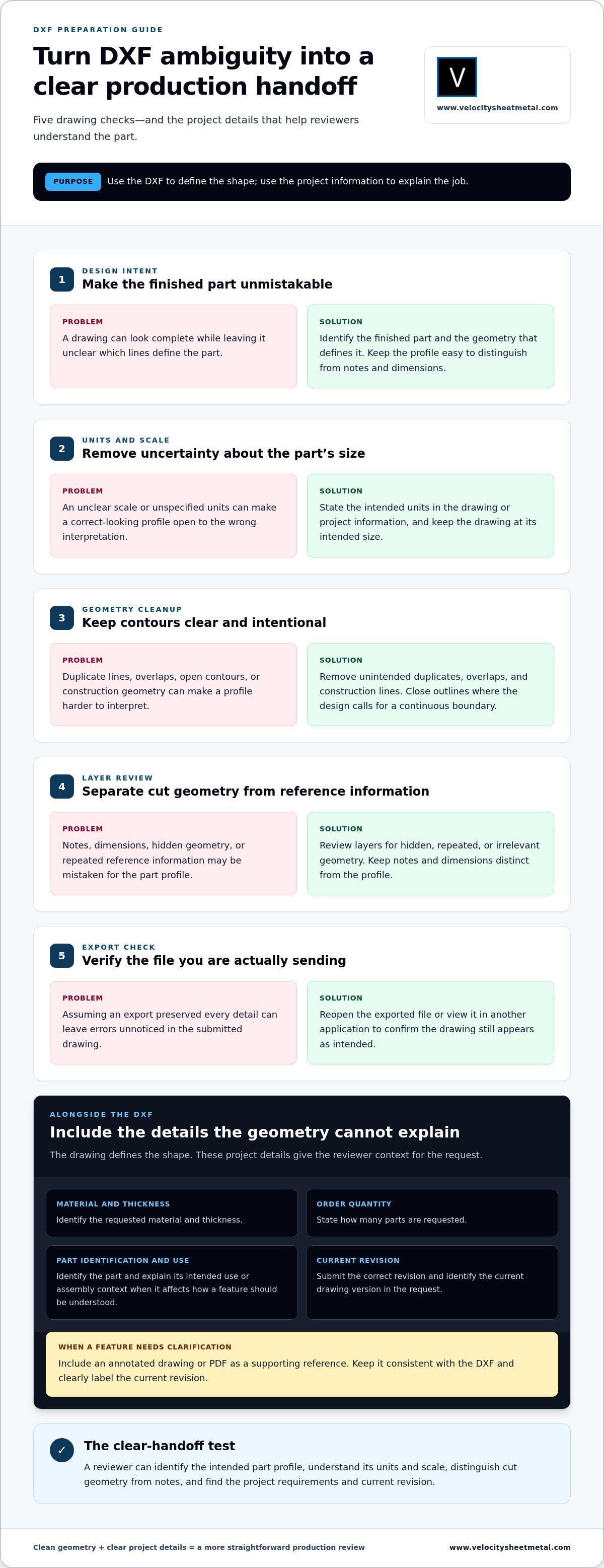
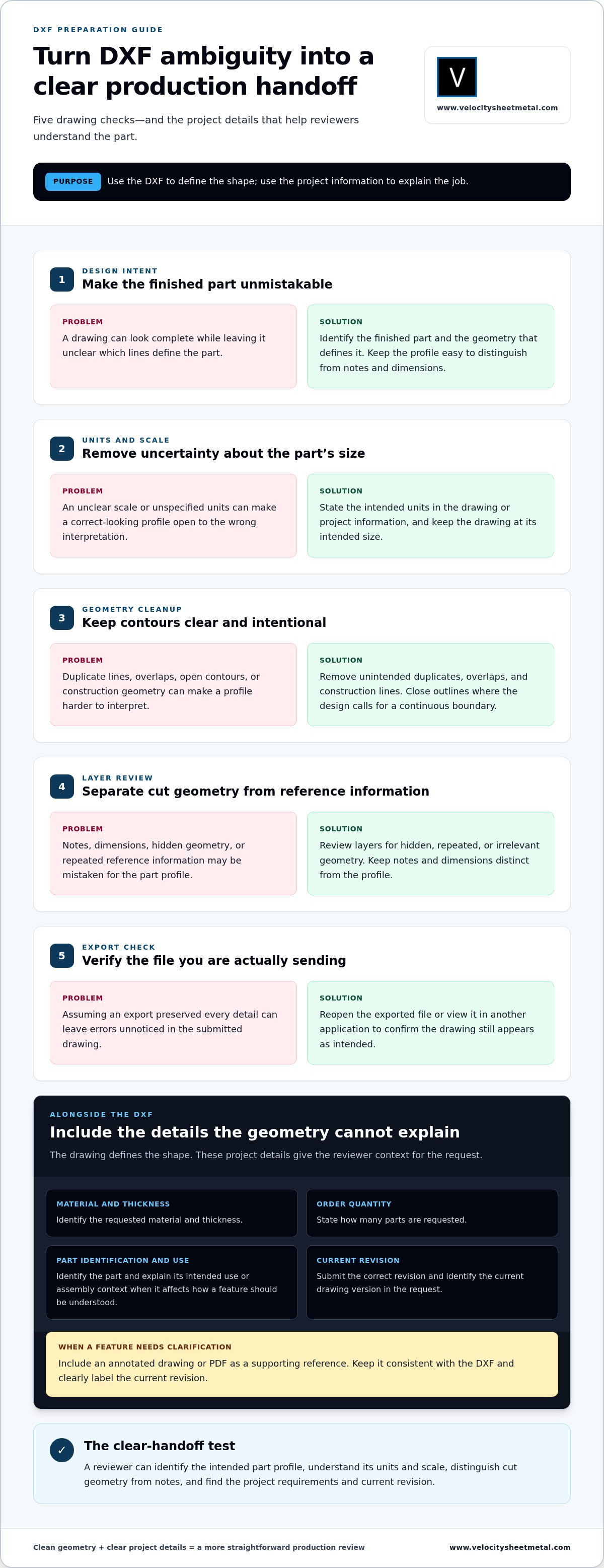
A clean file starts with a clear design decision: what shape should be made, and which lines define the part? Before exporting, work through the drawing in order. This sequence helps reduce ambiguity during review and keeps the file aligned with the project request.
- Confirm design intent. Identify the finished part and the geometry that defines it.
- Set units and scale. Make the intended measurement system clear and keep the drawing at its intended size.
- Clean the geometry. Remove duplicate lines, overlaps, and construction lines that aren’t part of the design.
- Review layers. Separate the part profile from notes and other reference information.
- Export and check. Reopen the exported file or view it in another application to confirm the drawing still appears as intended.
DXF is an exchange format used to move drawing information between software. For a straightforward overview of the format and its uses, see Adobe’s guide to DXF files. The format alone doesn’t make a file production-ready. The geometry and project details still need to communicate the intended part clearly.
Clean up geometry, layers, and scale
Each part profile should be easy to identify and free from unintended overlaps. Duplicate lines can make it unclear whether a contour is one edge or two. Open contours may leave uncertainty about where a profile begins or ends. Check that outlines are closed where the design calls for a continuous boundary. Remove construction geometry that isn’t intended for cutting, and keep dimensions or notes distinct from the profile.
Use clear units and preserve the intended drawing scale. Review layers for hidden, repeated, or irrelevant geometry before export. These checks don’t replace a production review, but they make the drawing easier to interpret. After exporting, inspect the file itself rather than assuming the export preserved every detail correctly.
Package the drawing with useful part details
The DXF describes geometry, but it may not explain the whole job. Include the requested material and thickness, order quantity, part identification, and current drawing revision with the project request. These details give the reviewer context and help distinguish the approved design from older files, especially when a project includes several similar components.
If a dimension, feature, or orientation could be misunderstood from the DXF alone, include an annotated drawing or PDF as a supporting reference. Keep it consistent with the DXF, and label the current revision clearly. The reference should clarify design intent, not introduce a conflicting version of the part.
For a DXF file for laser cutting service, clean geometry and useful project information create a clearer handoff. Velocity Sheet Metal provides custom laser cutting services as part of its precision sheet metal fabrication work, connecting a defined digital drawing with production review.
DXF Review for Laser Cutting: What to Check Before Production
A production review checks whether the drawing communicates a clear, manufacturable part. It can surface questions about the profile and project requirements, but software won’t necessarily catch every error or interpret design intent for you. A DXF defines geometry; it doesn’t necessarily state the material, thickness, quantity, or functional requirements needed to assess the full request.
Review also depends on the job. Tolerances and production capabilities are project-specific, so don’t assume a single standard applies to every part. State critical requirements explicitly, then consider the drawing and supporting information together.
Which drawing issues can create production questions?
Check whether the file tells one clear story. Unclear units can make the intended size uncertain. Overlapping lines or duplicate profiles may look like a single edge on screen but leave questions about the geometry. Incomplete contours can make the finished outline unclear. An outdated or unlabeled revision can also create doubt about which design is current. Review the digital profile, not just the dimensions printed beside it: visible measurements help people interpret a drawing, but they don’t necessarily define the cutting geometry.
What should accompany the DXF during review?
Give the reviewer enough context to understand the part. Include the requested material, thickness, and quantity, along with the part identifier and current revision. A brief description of the intended application can explain why a feature matters, especially when fit or function depends on it. If the DXF doesn’t convey design intent clearly, attach a dimensioned reference drawing or PDF and keep it consistent with the submitted file.
Distinguish essential requirements from general reference information. For example, identify a hole pattern or edge as critical if its position affects assembly. If a tolerance applies to a particular feature, call it out directly in the drawing or project notes rather than expecting the reviewer to infer it. Avoid adding unsupported tolerances as a blanket assumption; required precision and feasible production methods depend on the project.
- File clarity: Confirm the intended profile is distinguishable and the revision status is clear.
- Part context: State the material, thickness, quantity, identification, and application.
- Critical requirements: Mark important features and applicable tolerances explicitly.
- Supporting reference: Include a dimensioned drawing when it resolves ambiguity not shown by the DXF.
This information supports a focused review before production. It separates questions about the drawing from questions about the part’s requirements, helping the digital handoff move forward with fewer assumptions.
How to Submit a DXF File for a Laser Cutting Service
A useful submission is more than an attachment. It brings the current drawing together with the information needed to understand the part and review the request. Keep the handoff organized from final file preparation through clarification and approval. Clear file control makes it easier to identify the current design and reduces avoidable back-and-forth, without assuming a particular production timeline.
Build a complete laser cutting request
Before sending the request, gather the DXF, any dimensioned reference drawing, and the project details that apply. Include material, thickness, quantity, part identification, and drawing revision. If the component’s intended use affects how a feature should be interpreted, describe that briefly. A mounting plate, for example, may have a hole pattern whose position matters to assembly.
For multiple components, group related files and use consistent names so each drawing can be matched to its part. A simple naming pattern can include the part identifier and revision. Avoid filenames such as “final” or “final-new” on their own. They don’t reliably distinguish an approved drawing from an earlier version.
- Drawing: Attach the intended DXF and any reference document that clarifies it.
- Project details: State material, thickness, quantity, and intended application where relevant.
- Revision control: Identify the current revision in both the file name and request details.
- File organization: Match each file to a part identifier, especially for a group of components.
For broader context on evaluating a supplier and planning a request, the precision laser cutting services buyer guide covers considerations beyond the drawing itself.
Review clarifications and approve the correct revision
If a reviewer asks about geometry, material details, or a specification, resolve the question before the part moves forward. Reply with a direct answer tied to the part identifier. If the answer changes the design, update the drawing rather than relying on an email note that could become separated from the file.
Issue the revised file with a clearly updated revision identifier, and mark the prior version as obsolete in the request record. Before approval, compare the production file with the intended design: check the part identity, profile, supporting dimensions, and revision. This final comparison helps prevent an outdated attachment from being mistaken for the approved drawing.
A clear request helps production review focus on the part instead of sorting through conflicting files. For a prepared component drawing, submit your part for custom laser cutting with its supporting project details.
From DXF File to Finished Part With Velocity Sheet Metal
A clear DXF handoff sets up the next step: reviewing the part for custom laser cutting and coordinating production around its requirements. Velocity Sheet Metal provides custom laser cutting as part of its precision sheet metal fabrication capabilities, supporting projects that need a defined digital profile turned into a physical component.
The drawing is one part of the production picture. Material, thickness, quantity, intended use, and critical features help frame the review. With those details alongside the current file, the team can assess the request in context and address questions before the design moves forward. This coordination connects the digital drawing to the part the project needs, while recognizing that requirements vary from job to job.
Coordinate laser-cut parts with broader fabrication needs
Some components are complete as flat, laser-cut parts. Others are one stage in a larger fabricated assembly. If the design calls for formed features, CNC press brake bending may be relevant after cutting. The required geometry and project specifications guide that coordination. For more on formed sheet metal components, explore CNC press brake services for OEMs.
Keeping related work connected helps make the part’s role in the assembly clear. A flat profile intended for later forming, for example, has different project context from a component used as cut. Share the design intent so the review can consider the part as a whole, rather than treating the DXF as an isolated shape.
Move a project from digital drawing to production
Organized files, clear revision control, and complete project details give production review a focused starting point. They help distinguish the intended design from outdated versions and make specific questions easier to resolve. For customers managing projects across locations, Velocity Sheet Metal serves customers nationally, ships nationwide, and supports on-demand part production. Consistent part identifiers and drawing revisions can help keep project information aligned across repeat requests.
A well-prepared DXF file for laser cutting service is a useful bridge from design to fabrication, but it works best alongside clear requirements and communication. When the drawing and project details are ready, discuss your custom laser cutting project.
Turn Your Drawing Into the Next Production Step
A well-prepared DXF file for laser cutting service can become more than a one-time handoff. Treat it as a controlled production document. Keep the approved revision with the project record, and carry the same part identifiers into future requests. This gives your team a clearer starting point when designs change, quantities grow, or components return for another production run.
Bring the drawing and its project context together. Velocity Sheet Metal provides custom laser cutting and precision sheet metal fabrication, with on-demand part production for contractors, engineers, makers, and OEMs, plus nationwide shipping. Include the design intent and requirements so the request can move into a focused production review.
Discuss your custom laser cutting project and move your design toward a fabricated part. A clear handoff is a strong start for your next component.
Frequently Asked Questions
What is a DXF file for laser cutting?
A DXF file for laser cutting service carries vector-based drawing data that can guide the shape of a flat part. It represents geometry as digital entities rather than as a photograph or screenshot, making it useful for transferring a designed profile into a manufacturing workflow. The file still needs to match the intended part, and project information may be needed to clarify requirements the geometry can’t express.
Can I use a DXF file created in any CAD program?
Not necessarily. CAD programs can export DXF files differently, and compatibility may depend on the file version and the entities used in the drawing. Before submitting, reopen the exported file in a viewer or CAD application and check that curves, holes, and outlines appear as expected. If the export changes the geometry or scale, correct the source drawing and export it again rather than editing an uncertain copy.
How do I make sure my DXF file is drawn to scale?
Set the drawing to the intended size in model space and use a clearly defined unit system. Then check a known feature, such as the overall width of a panel, in the exported file against its intended measurement. A viewer’s zoom level doesn’t change the actual dimensions. If you also provide a printed or PDF reference, make sure its stated dimensions agree with the digital drawing.
What information should I send with a DXF file for a cutting quote?
Alongside the file, provide the part name or identifier, material, thickness, quantity, and current revision. Note the intended application if fit, orientation, or a particular feature affects how the component should be understood. For a group of parts, map each identifier to its drawing and requested quantity. This helps distinguish similar components and gives the request enough context for a useful production review.
Do DXF files need closed shapes for laser cutting?
A profile intended to define a continuous outer boundary should generally form a closed contour. Internal cutouts, such as holes, also need clearly defined geometry. Some designs include intentional open features, so closing every line without considering design intent can change the part. Inspect endpoints at corners and joins, and make sure any open geometry is deliberate and explained in the supporting drawing or request.
Can a laser cutting service work from a PDF instead of a DXF?
Sometimes, but a PDF isn’t automatically equivalent to a production-ready CAD file. A vector PDF can preserve outlines, while a scanned or raster PDF is essentially an image and may not define usable cutting geometry. A PDF can be valuable as a dimensioned reference for design intent. Keep the source CAD drawing available, and don’t treat a visual preview as proof that the scale or geometry is correct.
What happens if a DXF file has overlapping or duplicate lines?
Overlapping or duplicated entities can make it unclear whether the drawing contains one intended edge or multiple paths. Depending on the software workflow, repeated geometry may prompt questions or affect how the cut is interpreted. Don’t assume the file will automatically identify and remove duplicates. Inspect the drawing at close zoom, clean up repeated entities in the source file, then export and review the updated version before submitting it.